Hi
AndrewT and other experienced guys
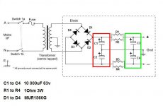
If I build a PS like the attachment and I do not have enough fund to spend on boutique caps which pair should be the better quality
The one which marked by red or the one with green.
I remember you wrote something about these somewhere but almost impossible to find it especially when I need the information
I build a dual mono amp so that extra 4PC caps")
Thank you
Greetings
AndrewT and other experienced guys
If I build a PS like the attachment and I do not have enough fund to spend on boutique caps which pair should be the better quality
The one which marked by red or the one with green.
I remember you wrote something about these somewhere but almost impossible to find it especially when I need the information
I build a dual mono amp so that extra 4PC caps
Thank you
Greetings
Attachments
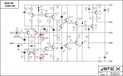
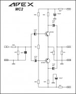
Apex AX-16
Dear apexaudio
Greeting...........
the amplifier works fine........
i have some query
++++++++++++++++++++++
i have tried to use it in a guitar amplifier. but the problem is some extra low frequency is passing through it, which is a problem..
Now if i change some cap in the circuit, would it be done the job?
and how can i boost its gain a little??
i am using 24v - 0 - 24v transformer
so what do u think??
Thanks, is this red line jumper from 'J' to 'J'?
Dear apexaudio
Greeting...........
the amplifier works fine........
i have some query
++++++++++++++++++++++
i have tried to use it in a guitar amplifier. but the problem is some extra low frequency is passing through it, which is a problem..
Now if i change some cap in the circuit, would it be done the job?
and how can i boost its gain a little??
i am using 24v - 0 - 24v transformer
so what do u think??
Attachments
Dear apexaudio
Greeting...........
the amplifier works fine........
i have some query
++++++++++++++++++++++
i have tried to use it in a guitar amplifier. but the problem is some extra low frequency is passing through it, which is a problem..
Now if i change some cap in the circuit, would it be done the job?
and how can i boost its gain a little??
i am using 24v - 0 - 24v transformer
so what do u think??
This can help...
Attachments
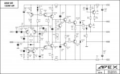
40db high pass? ok
thanks i will check
n what about the gain?? how can i control it? R2 or R8
R8, but gain is high, what guitar preamp you use?
That post5321 diagram is wrong.Hi
AndrewT and other experienced guys
If I build a PS like the attachment and I do not have enough fund to spend on boutique caps which pair should be the better quality
The one which marked by red or the one with green.
I remember you wrote something about these somewhere but almost impossible to find it especially when I need the information
I build a dual mono amp so that extra 4PC caps
Thank you
Greetings
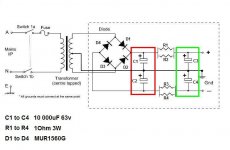
It shows the centre tap going to some "ground".
NO !!!!
The centre tap must go to the first smoothing capacitors Zero Volts junction.
The certre tap wire passes charging pulses. These pulses also pass along the two other secondary wires. You must twist these as a triplet.
The output after the rectifier also passes these pulses. These too must be twisted with the centre tap wire as a triplet. This triplet feeds the first smoothing capacitors.
Why don't Members read and implement ?
Last edited:
For a opamp based power amp without VAS stage, what do you think about this one :

Driven by Op Amp High-performance Amplifier Circuit - Electrical_Equipment_Circuit - Circuit Diagram - SeekIC.com
Thanks
Driven by Op Amp High-performance Amplifier Circuit - Electrical_Equipment_Circuit - Circuit Diagram - SeekIC.com
Thanks
guitar preamp out is approx 600mv......... should i boost more
Increase preamp out to 1V
For a opamp based power amp without VAS stage, what do you think about this one :
Driven by Op Amp High-performance Amplifier Circuit - Electrical_Equipment_Circuit - Circuit Diagram - SeekIC.com
Thanks
Amp without VAS must have folower OS and all voltage gain must be with OP amp. You have high voltage gain with transistors in your circuit.
Regards
That post5321 diagram is wrong.
It shows the centre tap going to some "ground".
NO !!!!
The centre tap must go to the first smoothing capacitors Zero Volts junction.
The certre tap wire passes charging pulses. These pulses also pass along the two other secondary wires. You must twist these as a triplet.
The output after the rectifier also passes these pulses. These too must be twisted with the centre tap wire as a triplet. This triplet feeds the first smoothing capacitors.
Why don't Members read and implement ?
AndreT
You did not answered to my question
The schematic how it is drawn is not correct and correct. The center tap marked as a Ground.
The caps bank center marked as a Ground
The two GROUND must or will be connected together before connected to the PC boards etc..
Also will be connected to the amplifier case true a 10R 3W resistor.
The reason the sketch made these way because to small ( already over crowded) and if I connect the two ground it will be even more over crowded.
Thank you for reminding me.
I knew that. Now can you please answer the original question I turned to you.
Thank you very much
Cheers
hola amigos de esta pretigiosa pagina, queria saber encuanto queban el bias de esta apex ax-11y si es respecto a tierra o gnd gracias

English only please.
Hello friends this prestigiously page, I wanted to know as soon as queban the bias of this apex ax-11 if it is on land or gnd thank you
If you build it like shown or like you have just described it will perform badly.
So badly, it will completely obscure any effect from different capacitors.
Sort the diagram first.
then we can talk about whether some different capacitors might help.
OK AndrewT here we go
In many schematic diagrams they use the Ground symbol like how it was. That mean all those ground connected together (in a star ground) unless describe it different way.
Sometimes signal Ground is separated from main but that usually mentioned. That would a different topic. We talk here about PS.
Greetings
Attachments
That is correct.
Many can't see that this is different from your previous post.
Now let's refine it.
the three wires from the secondary into the box. These must be close coupled for minimal loop area and even better if twisted as a triplet.
The three wires from the rectifier to the first smoothing caps must also be close coupled and preferably twisted as a triplet.
The three wires from the first smoothing to the resistor banks must be close coupled.
The three wires to the second smoothing must be close coupled.
The three output wires must be close coupled.
This twisted triplet minimises the EMI that can escape into the surroundings of the PSU.
Finally notice you have labeled Gnd as separate from the junction of the last smoothing bank. Again this is important.
Do NOT bring your common voltage reference to the smoothing bank junction.
The first smoothing bank capacitors are subjected to high ripple.PS like the attachment and I do not have enough fund to spend on boutique caps which pair should be the better quality
The one which marked by red or the one with green.
Ensure you have sufficient ripple capacity so that they operate cool.
many small caps usually have higher ripple capacity than one bigger capacitor. Use (cheap) commercial/industrial electrolytics.
The transient current demand of the amplifier is met by the last smoothing bank.
The fastest transients are already fed from the local HF decoupling.
The medium speed transients are fed from the local MF||HF decoupling.
The PSU cap bank supplies the LF transient demand and the DC demand.
It is my belief that if the local decoupling is done correctly AND adequately that the SQ of the amplifier is not affected at all by the earlier capacitors in the PSU stages.
Only this last has a small effect and much of that is restricted to the LF SQ.
If a Builder claims that HF SQ is affected by this last cap bank, then I immediately think they have not designed in adequate local decoupling and I discount their claim as that from an incompetent.
Good quality commercial/industrial capacitors will do a good job for this last capacitor bank. But they must be adequately sized to release the current with minimal voltage modulation.
Last edited:
Thank you AndreT
Very useful information, appreciated!
These PS can be used with several Apex design, if someone interested a couple page earlier you can find the layout which is professional thanks to Alex.
AndrewT I see many commercial amplifier use only one cap bank. My opinion that would do less adequate job like CRC or CLC set up.
There is a amplifier I will build it soon, the designer of the circuit is someone who earned a lot of respect with his amps, designs, upgrades he done.
I do not post the schematic here, I do not want to pollute these tread with circuit nothing to do with Apex design.
These PS is useful here to all DIY-ers. And the information you gave that to!
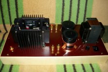
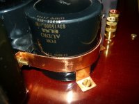
So the guy used only one high quality cap bank 15 0000uF Elna for audio big sized high end caps please see the attachments......
Several guy built the amplifier and claim it has a supper performance, very high quality sound..
My opinion CRC or CLC even smaller value caps give better job.
Can you comment on that please
Thank you one more time
Greetings
Very useful information, appreciated!
These PS can be used with several Apex design, if someone interested a couple page earlier you can find the layout which is professional thanks to Alex.
AndrewT I see many commercial amplifier use only one cap bank. My opinion that would do less adequate job like CRC or CLC set up.
There is a amplifier I will build it soon, the designer of the circuit is someone who earned a lot of respect with his amps, designs, upgrades he done.
I do not post the schematic here, I do not want to pollute these tread with circuit nothing to do with Apex design.
These PS is useful here to all DIY-ers. And the information you gave that to!
So the guy used only one high quality cap bank 15 0000uF Elna for audio big sized high end caps please see the attachments......
Several guy built the amplifier and claim it has a supper performance, very high quality sound..
My opinion CRC or CLC even smaller value caps give better job.
Can you comment on that please
Thank you one more time
Greetings
Attachments
Last edited:
- Home
- Amplifiers
- Solid State
- 100W Ultimate Fidelity Amplifier