We all thank you for all your work!I tried with Sprint 6 and just wasted a couple hours with out any good result.
Please ,post schematic with values of component and I will layout for you
Regards,Alex
I tried with Sprint 6 and just wasted a couple hours with out any good result.
Please ,post schematic with values of component and I will layout for you
Regards,Alex
Hi Alex
First of all I want to give you a big thank you for your help (offer)
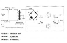
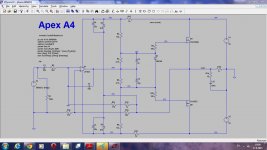
Here is the schematic, if you are too busy make it simple as possible
C1 to C4 = 4 X 10 000uF 63V
D1 to D4 = 4 X MUR1560G (TO220 case) Heatsink not necessary or max 2 diode on 1 heatsink, the easiest way.
R1 to R4 resistors 1 Ohm 3Watt
If you already has something similar in your library please let me know.
Thank you very much one more time
Greetings gabor
Attachments
Hi Gabor ,
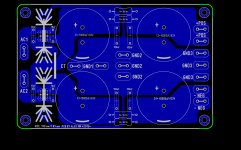
I have layout this morning, first PCB of PSU and I hope you like it.......
Regards,Alex
I have layout this morning, first PCB of PSU and I hope you like it.......
Regards,Alex
Attachments
Last edited:
Nice job,just mention ...two leds cost nothing. Add one for each railHi Gabor ,
I have layout this morning, first PCB of PSU and I hope you like it.......
Regards,Alex
Right ,but leds are on amplifier PCB near rail fusesNice job,just mention ...two leds cost nothing. Add one for each rail
Hi Gabor ,
I have layout this morning, first PCB of PSU and I hope you like it.......
Regards,Alex
Alex that is excellent! Super nice work.
Thank you very much from the bottom of my hearth
I hope other people will use it to..
Greetings gabor
Alex if I could ask a small mode not because the layout is not supper
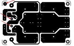
Based on my experience the home made PC boards by iron transfer sometimes not the best method to produce a great or good quality PC boards.
So many times small pieces rings or thin traces not strong enough to support the component.
In our case the heatsink inside ring it would be better if you could increase the size a bit bigger with smaller inside hole for drilling
Also the PC board 4 suspending hole would be better without those small holes and a smaller inside hole for drilling if you have that option or just place the heatsink hexagonal soldering eye there. These mode not as important like the heatsink only screws goes there no need for soldering..
Again these not because the layout is not perfect! With these mode the iron transfer would give better result. Many of us produce our PC boards these way.
Please see the attachment I made the mode so you can see it but not nice like your job.
Thank you very much
It is a hard feeling to ask you because you made a perfect job all components feet nice and perfect.
With photo transfer or industrial produce can not be better these layout
Only if you have some spare time to do that
Attachments
Last edited:
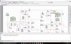
Still4,I had to pull the IC to get the rails high enough to activate the zeners. I didn't go much higher for fear of burning something. Attached is a marked up schematic
have you had any answers to your voltage questions?
I don't think this circuit works. I can't get it to work in Ltspice or in the real world. I made a spice file for others to test and no one has responded. I'm not doing any more with it until Mile returns or someone else takes enough interest to either build one or at least make the spice file work so we have something to show it works.
I don't think this circuit works. I can't get it to work in Ltspice or in the real world. I made a spice file for others to test and no one has responded. I'm not doing any more with it until Mile returns or someone else takes enough interest to either build one or at least make the spice file work so we have something to show it works.
Played with A4 on multisim for few days. First thing I checked was bias current which was 550mA even with two diode and with one diode its less than 1mA. You can jumper D3 with wire and use trimpot across D8 on your layout.
From my understanding of this circuit, front end cannot be checked separately. Because IC1 supply voltage +16V, -16V are with reference to output and they are floating with reference to ground. If output is at 30Vp positive swing than voltage at IC1 with reference to ground will be +46, +14 and for 30Vp negative swing -14, -46.
Regards,
Sonal Kunal
Attachments
Last edited:
I have created a spice file but it doesn't work so maybe someone can have a look at it.
You have a mistake in your spice file. You have connected 100K resistor (R1) in series with input signal source (V3), while they should be connected in parallel. After you fix that, the simulation will run and produce a sensible output.
However, something is still screwy with LTSpice and this simulation. If you use "Normal" spice solver, output will show some spurious oscillations at the beginning. Switching to "Alternate" spice solver will result in clean output without oscillations. In case you don't know, which spice solver to use for simulation can be set in LTSpice control panel.
I don't think this circuit works. I can't get it to work in Ltspice or in the real world. I made a spice file for others to test and no one has responded.
Hi Terry, I installed LTspice and used direction given mrmax063 it works. I made some changes values of resistor with regards to multisim to R15 and R16 because gain was low, also added resistor in series with R15.
Regards,
Sonal Kunal
Attachments
Hi Terry, I installed LTspice and used direction given mrmax063 it works. I made some changes values of resistor with regards to multisim to R15 and R16 because gain was low, also added resistor in series with R15.
Regards,
Sonal Kunal
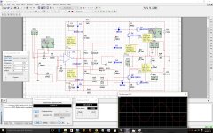
This is what I see with your file.
Attachments
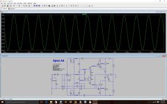
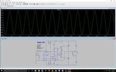
it works...
Attachments
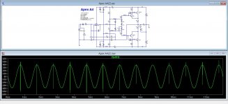
Terry, it was done as mrmax063 suggested using "Alternate" spice solver. Using original values it oscillate once in the beginning.
But look at UltimateX86 file it works perfect using"normal" spice solver.
Regards
Sonal Kunal
But look at UltimateX86 file it works perfect using"normal" spice solver.
Regards
Sonal Kunal
Attachments
Last edited:
- Home
- Amplifiers
- Solid State
- 100W Ultimate Fidelity Amplifier