Fixed file.
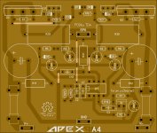
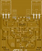
That's really cool! I am just learning Sprint. I shrunk youR layout down so I could fit two boards side by side on a 6-1/2" PCB. If you don't mind, would you look it over and see if I missed anything? I hope you don't mind me doing this. Just trying to learn.
Blessings, Terry
Attachments
Last edited:
Fixed file.
Hi BC109,
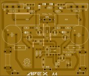
I'm confused. What schematic did you use for the A4? The only schematic I can find is in post #5230. This layout doesn't follow that one.
Thanks, Terry
Hi Terry,
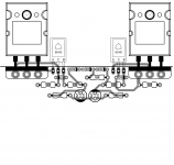
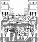
BD139 and BD140 plastic side will be towards heat sink in current orientation.
I have started layout for A4.(Ignore copy paste it will be corrected when layout is completed)
Regards,
Sonal Kunal.
Yes, I just noticed that it called for BD139/140. This layout is pinned for TO-220 so I used those. Not sure how that will affect the circuit.
Attachments
Hi Terry,
BD139 and BD140 plastic side will be towards heat sink in current orientation.
I have started layout for A4.(Ignore copy paste it will be corrected when layout is completed)
Regards,
Sonal Kunal.
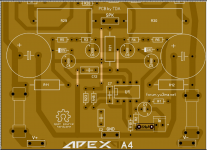
In the interest of learning I've tried switching things around to utilize the BD139/140. Tell me what you think.
Thanks, Terry
Attachments
In the interest of learning I've tried switching things around to utilize the BD139/140. Tell me what you think.
Thanks, Terry
You have keen eyes, at following schematic on pcb layout.
")
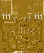
Completed layout of A4 last night.
Regards,
Sonal Kunal
Attachments
Still4,
have you swapped in an ECB device (To126), where the PCB is laid out for a BCE device (To220)?
I'm not sure I understand the question. The schematic has BD139/140 for the drivers. BC109 used TO-220. Since I am modifying his layout I tried to swap in TO-126 devices to match the schematic. I'm trying to learn how to use Sprint so this is good practice for me. I'm also cheap and wanted to fit two channels on one board and my boards are only 6.5" wide.
I'm not sure I understand the question. The schematic has BD139/140 for the drivers. BC109 used TO-220. Since I am modifying his layout I tried to swap in TO-126 devices to match the schematic. I'm trying to learn how to use Sprint so this is good practice for me. I'm also cheap and wanted to fit two channels on one board and my boards are only 6.5" wide.
Nice to see you're getting somewhere with Sprint. Half the fun of making an amp is designing it.
still4given, have you tried to look at youtube for some videos about sprint program? one 10 minute video has shown me more than two pages of text would...
Yes I have watched a few. Juan Vargas made one for me that has helped. Learning where to find the right tools is the biggest hurdle. I am slowly learning it. Modifying layouts such as this one is helping.
Now for testing. OSCILLATOR.
It will play a sine wave but it has some ugly stuff one shoulder. Square wave send it into almost instant oscillation. Thank God for the light bulb.
Now a couple of things to note. I am using a TL071 for the OP, 2SC3423-Y/2SA1360-Y for drivers and MJL21193/4 for the outputs.
Everything else is per schematic. Waiting for suggestions.
Last edited:
You can add 220pF capacitor after 3K9 resistor connecting to signal ground and check. Then try to add capacitor from base of to collector of 2SC3423-Y/2SA1360-Y parallel with diode on copper side. Check with 100pF first.
Regards,
Sonal Kunal.
Regards,
Sonal Kunal.
Attachments
Last edited:
I am using a TL071 for the OP, 2SC3423-Y/2SA1360-Y for drivers and MJL21193/4 for the outputs.
May be AndrewT can tell properly, 2SC3423-Y/2SA1360-Y are 50mA rated.
May be AndrewT can tell properly, 2SC3423-Y/2SA1360-Y are 50mA rated.
The cap on the 3k9 was a fail. Sent the bias through the roof. I had already tried caps on the drivers c-b. They didn't help. It could be the drivers. I'll swap in some BD130/140s and see what happens. I used the 2S devices because it was hard to imagine the BD's as drivers and +-55V rails. I suppose I shouldn't have used the MJL21193/4 either. Just trying to find a home for them. I had hoped they would work since the ones spec'ed were slow devices.
I have created a spice file but it doesn't work so maybe someone can have a look at it.
Attachments
- Home
- Amplifiers
- Solid State
- 100W Ultimate Fidelity Amplifier