ax400
how about sound qualty??


thk.
arif smD
Not tesed yet.... with 64 VAC
how about sound qualty??
thk.
arif smD
Here are some scope shots. I still have a ground hum. The input is creating a ground loop. I'm going to try lifting the input ground with a resistor and see if that helps.
Nice, can you post ground wireing circuit or picture of your A40?
Regards
Hello guys
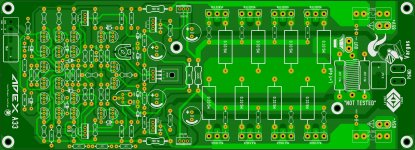
I spend some time with the A33 schematic and then today I can say I almost done with the layout and this is the first time that I do not have any jumper on the PCB jejejejejeje
I will continue checking here I just thought to show you guys
Regards
Juan
I spend some time with the A33 schematic and then today I can say I almost done with the layout and this is the first time that I do not have any jumper on the PCB jejejejejeje
I will continue checking here I just thought to show you guys
Regards
Juan
Attachments
I've got a question about a lifted input ground. If you want to lift the input ground, should the NFB ground be attached there?
Yes input ground and NFB ground must be on same point
Hello guys
I spend some time with the A33 schematic and then today I can say I almost done with the layout and this is the first time that I do not have any jumper on the PCB jejejejejeje
I will continue checking here I just thought to show you guys
Regards
Juan
Nice work
Regards
Yes input ground and NFB ground must be on same point
Would the ground scheme in the attached be correct?
Thanks, Terry
Attachments
Hi Guys,
I tried lifting the input ground on one channel but didn't see any change in the level of the hum so I went through the board again and re-flowed a few of the solder joints around the ground planes and the ground hum is now miniscule. Bypassing the ground lift was actually quieter so I put it back to stock. I didn't get a chance to A/B it to the A33 but did A/B it against the Honey Badger and they are too close to call. This is a great sounding amp.
A couple of things of notice. I used 4k7 for the offset trimmer. Offset is a little touchy to adjust and it tends to float between +-20mv offset. It's plenty low but not real solid. The bias tends to float around a bit as well. I just have it on a smallish heatsink right now but still the bias seems a little slow compensate. I will get them mounted to large heatsinks and see if the bias will settle.
Blessings, Terry
Hello guys
I spend some time with the A33 schematic and then today I can say I almost done with the layout and this is the first time that I do not have any jumper on the PCB jejejejejeje
I will continue checking here I just thought to show you guys
Regards
Juan
Hi
I do like the A40 a lot.
If PC boards will be available very likely I will build it.
Vargas if you can increase the size of the input capacitor that would be great.
Good quality caps usually comes in a large size a la crossover capacitors.
Only I mention that because you got a loot of room there.
Great jobbbbbbbb!!
Greetings
Hello guys
I spend some time with the A33 schematic and then today I can say I almost done with the layout and this is the first time that I do not have any jumper on the PCB jejejejejeje
I will continue checking here I just thought to show you guys
Regards
Juan
Hi
I do like the A40 a lot.
If PC boards will be available very likely I will build it.
Vargas if you can increase the size of the input capacitor that would be great.
Good quality caps usually comes in a large size a la crossover capacitors.
Only I mention that because you got a loot of room there.
Great job, nice layout!
Greetings
That can be done, what size PD distance are those input caps are ? I might be able to add different sizes feel free to give input cap suggestions I don't mind at all
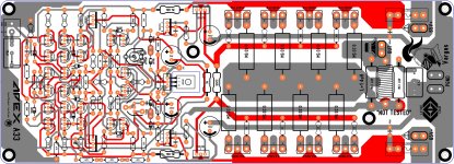
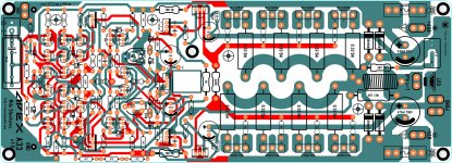
, well about the new A33 layout so far I have not find any error yet or better say "bugs" so far, I might order a few I'm not sure yet, because I already copy the Apex HV23 mosfet amp that one is a nice layout, A40,A33, HV23, is a lot of them that I would like to try out  ( I have to chose one of them is hard man )
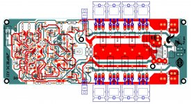
 here is the image of the layout is a double layer and good things is that there is no jumpers on this one "I was lucky indeed" jejejejeje
Regards
Juan
Attachments
Last edited:
Today I mounted the boards on heatsinks so I could give them a good test. The amp sounds very good but the thermal compensation is not affective. The hotter the amp gets the higher the bias goes. Something need to change there. As I said before, the scale is a little small so the devices are pretty tight together but I would think that would make the comp sensors more affective. The other thing is the offset is very unstable. As the amp heats up the offset can climb pretty high.
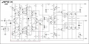
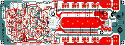
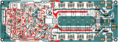
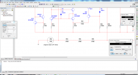
Hello guys I have spend a few hours on the Apex A33 and I did found two errors now they are fixed I will continue analyzing all the layout and I did some changes and traces are a bit larger 1.5 mm I think it looks great, I have the idea of adding those 4 diodes at the end I'm not sure is that is a good idea or not "the idea I took it from the "Slewmaster" by OS probably I'm wrong what you guys think ?
Regards
Juan
probably I'm wrong what you guys think ? Regards
Juan
Attachments
Looks Good. I like it. Let me know if you decide to get a small run of these done. i'd be in for 2.
Me to.
Thank you
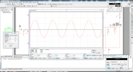
Hello guys I was simulating the A33 and I have good results also I have never seen a square wave as sharp as this one "of course this is my finds I'm not an expert" lol well good thing I simulated because now I have the part numbers so I can re-check the layout so now I can identified what part goes where according to simulation, I notice that I can not get a lot of power right away but I notice it keeps the THD really low even with high frequencies up to 20KHz I test it using 65V rails I forgot to ask mister Mile for correct rail voltages, to get more power I have to increase signal up to 1.3Vp 1KHz sine wave and is about 200W @4 ohms load and to 8 ohms about 100W but really nice low THD to 0.003% up or down a little bit this is just results of the simulation so now I have an idea that this will be a nice design to have  I will continue here checking "analyzing" as always
Regards
Juan
I will continue here checking "analyzing" as always Regards
Juan
Attachments
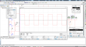
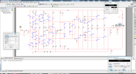
Hello guys I was simulating the A33 and I have good results also I have never seen a square wave as sharp as this one "of course this is my finds I'm not an expert" lol well good thing I simulated because now I have the part numbers so I can re-check the layout so now I can identified what part goes where according to simulation, I notice that I can not get a lot of power right away but I notice it keeps the THD really low even with high frequencies up to 20KHz I test it using 65V rails I forgot to ask mister Mile for correct rail voltages, to get more power I have to increase signal up to 1.3Vp 1KHz sine wave and is about 200W @4 ohms load and to 8 ohms about 100W but really nice low THD to 0.003% up or down a little bit this is just results of the simulation so now I have an idea that this will be a nice design to have
Regards
Juan
Nice work.
Regards
hello mister Mile
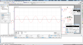
I have a question I was simulating with multism 13 and I notice that I can get even more power if I change only one value resistor from 47 to 33 ohms is that be ok to do ? I notice that I can get more power output and THD still good and low, at 1KHz and 1Vp sine wave @4 ohms load I get about 240W using 70V rails with 4 pairs and with same setting @8 ohms I get about 120W I mean I'm not pushing hard the simulations to it's clipping area, just let me know is that 45R resistor can be change or not, when you get time of course
Regards
Juan
I have a question I was simulating with multism 13 and I notice that I can get even more power if I change only one value resistor from 47 to 33 ohms is that be ok to do ? I notice that I can get more power output and THD still good and low, at 1KHz and 1Vp sine wave @4 ohms load I get about 240W using 70V rails with 4 pairs and with same setting @8 ohms I get about 120W I mean I'm not pushing hard the simulations to it's clipping area,
just let me know is that 45R resistor can be change or not, when you get time of course Regards
Juan
Attachments

Last edited:
- Home
- Amplifiers
- Solid State
- 100W Ultimate Fidelity Amplifier