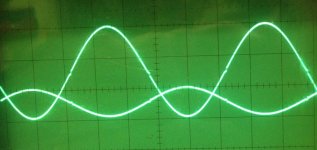
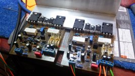
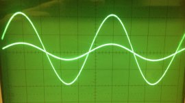
I already done with one chanel ...very easy to build, just need set bias and play.. picture show sine at 100khz, square at 10khz and 20 khz...
short video...
Apex A14 - YouTube
Nice work.
Regards
A9
Hi,
here is the first impression of the A9. It sings
It runs with + -36VDC. The offset is between 4 and 5 mV after 20 seconds (comes from 300mV when turned on). The quiescent current is 15mA. With this setup, it can be set with the trimmer between 12 and 15mA.
The gain is high. The picture shows the input with 0.1Vpp and the output is 6Vpp at 1kHz! How can I adjust it?
The switching point of the FETs can be seen?
The sound is warm and has a crisp, punchy bass. The highs are crystal clear and without any background noise. With the old speakers as test equipment very impressive!
Some advice to optimize ist?
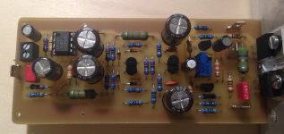
Layout can be changed. FETs should have more distance. It was tricky to mount it...
regards Olaf
Hi,
here is the first impression of the A9. It sings
It runs with + -36VDC. The offset is between 4 and 5 mV after 20 seconds (comes from 300mV when turned on). The quiescent current is 15mA. With this setup, it can be set with the trimmer between 12 and 15mA.
The gain is high. The picture shows the input with 0.1Vpp and the output is 6Vpp at 1kHz! How can I adjust it?
The switching point of the FETs can be seen?
The sound is warm and has a crisp, punchy bass. The highs are crystal clear and without any background noise. With the old speakers as test equipment very impressive!
Some advice to optimize ist?
Layout can be changed. FETs should have more distance. It was tricky to mount it...
regards Olaf
Attachments
olafk
Nice job !!
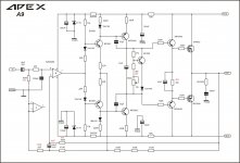
To decrease gain you must replace 22R resistor going to the signal GND, if you put 68R resistor the gain will be approx x30, if you put 47R the gail will be x42.
The bias at the driver stage is very low, the 5mA would be better IMHO (if you replace 3.9k resistor with 1.5k)
This is my next amp I am going to build but with bit different arangement, looks superb simple and nice.
Nice job !!
To decrease gain you must replace 22R resistor going to the signal GND, if you put 68R resistor the gain will be approx x30, if you put 47R the gail will be x42.
The bias at the driver stage is very low, the 5mA would be better IMHO (if you replace 3.9k resistor with 1.5k)
This is my next amp I am going to build but with bit different arangement, looks superb simple and nice.
Last edited:
Try to short the gnd lift resistor and scope again.Hi,
input without output shows a clean sinewave. I believe that is croostalk. I have to check the grounding. Input comes from a DDS signal generator.
At the moment everything looks (and sounds) very good. I will later make a few experiments with the gain and bias.
The corrected layout I will upload today evening.
What a nice amplifier. Thanks to Mile again!
regards Olaf
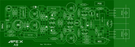
Nice work, schematic with new (red) values for fast DC servo, high bias and low gain.
Regards
Attachments
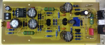
A9 ready
I have installed all the changes since the last schematic by Mile. Perfect! The sound is just great. Please do not ask how to explain it") . The offset is zero. Sine wave looks perfect.
. The offset is zero. Sine wave looks perfect.
Great!
I have made a few changes to the layout. On the component side you can see last installed values.
regards Olaf
See also my apex-autumn gallery
Many thanks
I have installed all the changes since the last schematic by Mile. Perfect! The sound is just great. Please do not ask how to explain it
. The offset is zero. Sine wave looks perfect.Great!
I have made a few changes to the layout. On the component side you can see last installed values.
regards Olaf
See also my apex-autumn gallery
Many thanks
Attachments
Last edited:
See also my apex-autumn gallery
Which one do you like most?
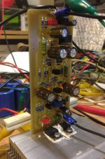
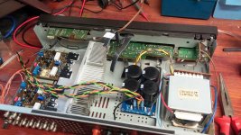
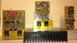
Second channel just finished.. there aren't any difficulties... I decided use my old Technics chassis for this amp....
Nice work, heatsinks from recicled PC
Regards
I have installed all the changes since the last schematic by Mile. Perfect! The sound is just great. Please do not ask how to explain it
Great!
I have made a few changes to the layout. On the component side you can see last installed values.
regards Olaf
See also my apex-autumn gallery
Many thanks
Many Thanks for this pcb, A9 is my favorite amp,
Regards
I have installed all the changes since the last schematic by Mile. Perfect! The sound is just great. Please do not ask how to explain it
Great!
I have made a few changes to the layout. On the component side you can see last installed values.
regards Olaf
See also my apex-autumn gallery
Many thanks
great job olaf - as usual!
what will you cook for winter? Many Thanks for this pcb, A9 is my favorite amp,
Regards
I like to build amps
A9 is one on the top of the favorites list. Unfortunately, I can never really decide.
Thanks and regads
Olaf
Nice work, heatsinks from recicled PC
Regards
yes, it will be new born amp from recycled material
- Home
- Amplifiers
- Solid State
- 100W Ultimate Fidelity Amplifier