Hurray!!!!!!!!!!!!!
Great news free drinks for everyone
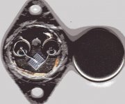
  But still how come they relabel their semiconductors? Is that in the manufacturing process?? Seems to me too the die looks like a genuine one.
I've also cracked my TIP2955/3055 to see a tiny miny die inside i'll post these ones too and drop the TIP35C/36C.Its actually after cracking those open that i decided to go for MJ15003/15004 given that the seller was telling me they were original parts
I'll modify the pcb and post it soon and purchase a pair of MJ15003/15004 for one amp before building the remaining ones.
Great news
free drinks for everyone But still how come they relabel their semiconductors? Is that in the manufacturing process?? Seems to me too the die looks like a genuine one.I've also cracked my TIP2955/3055 to see a tiny miny die inside i'll post these ones too and drop the TIP35C/36C.Its actually after cracking those open that i decided to go for MJ15003/15004 given that the seller was telling me they were original parts
I'll modify the pcb and post it soon and purchase a pair of MJ15003/15004 for one amp before building the remaining ones.
Andy L. Francis said:It looks genuine, although I became uncertain after reading your acetone-test.
Probably it's a re-labeled genuine ON device.
Could be. To me the die looks like a 2N5630 (or 6030). I've cracked open old ones in the aluminum case before fakes were prevelant and that's what I saw. Those are only rated 5A @ 30V DC SOA, but usually will take more. It could pass for a 15004.
I've also gotten burned by fake MJ15024's a few years back. Paralleled devices wouldn't share currents and solderability sucked. They were all labeled the same - with 9638 date code. I cracked them all open and some were the usual 2N3055 size die coated with silicone, and others looked just like the one above. Those might have passed an SOA test, and capacitances would have at least been close.
Those might have passed an SOA test, and capacitances would have at least been close.
Have you done an SOA test on them wg? In case yes do you know their SOA values?
Thanks
Goign ahead with transistor tester
Ok am moving ahead to build a transistor tester. Would ESP project 31
http://www.sound.westhost.com/project31.htm
be wise to build?
Thanks
Ok am moving ahead to build a transistor tester. Would ESP project 31
http://www.sound.westhost.com/project31.htm
be wise to build?
Thanks
Hi,
I don't know how they measure Vce0, but I suspect that a non destructive Vce0 test will pulse a high voltage through a very high resistance (effectively constant current source) and measure the slope of the Ic vs Vceo line as the pulse voltage is raised. At some high voltage the slope will flatten beyond some acceptable limit and that will define Vce0.
I don't know how they measure Vce0, but I suspect that a non destructive Vce0 test will pulse a high voltage through a very high resistance (effectively constant current source) and measure the slope of the Ic vs Vceo line as the pulse voltage is raised. At some high voltage the slope will flatten beyond some acceptable limit and that will define Vce0.
zeus_threat said:
Have you done an SOA test on them wg? In case yes do you know their SOA values?
Thanks
No, I didn't test those particualr phonies. Once they were opened up, what would have been the point? But I was surprised to see that *some* of the die were an expensive type (but not the right one). Maybe they were rejects the got cheap.
I originally built a couple of amps with two paralleled pairs of 5630 on +/-60 volt rails. Takes 4 ohms all day, but the supply drops to around 50V. I had friends build the same amp in college and no problems. I have since done some stress testing and no failures for a couple seconds at 50V at 4 amps. Only had one failure during that set of tests and it was at 70 volts. It was just hard-wiring the DUT as a current source and applying VCC, making it difficult to reconfigure. And of course it's destructive when it fails.
Thanks andrew i saw the RCA application note i know what you are talking about and i know its the best way to go but the thing is that am already not able to find a single valid genuine device here building that stuff with all that bjt in and relying on them is even worse. Thats why i elected the ESP project 31 though knowing i would end up blowing a lot of transistors. The variable high voltage PSU relies on a single transistor thats easier to handle 1 parameter at least . Maybe you can have a look at project 31 basically it aims at increasing voltage to find sudden increase in current and measure the CE voltage with open base.
That sudden increase in current can be enough to kill the transistor immediately but i got no choice. Do you know of any simple setup that would work instead?
Can you please explain your testing procedure wg i could go that way too.
Thanks again guys
. Maybe you can have a look at project 31 basically it aims at increasing voltage to find sudden increase in current and measure the CE voltage with open base. That sudden increase in current can be enough to kill the transistor immediately
but i got no choice. Do you know of any simple setup that would work instead?Can you please explain your testing procedure wg i could go that way too.
Thanks again guys
zeus_threat said:Can you please explain your testing procedure wg i could go that way too.
Thanks again guys
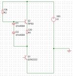
It was simple... Put a pair of 7 ohm 50 watt (surplus of course) resistors in parallel to get 3.5 and put it in the emitter circuit. Apply 15 volts to the base. Turn up the collector supply to 65 volts and press the button. DUT mounted on heat sink with fins in an ice bath. It's 200 watts at 50 volts. It won't test the very boundaries of premium ON devices, and it's a bit outside the SOA of some older types but screens well enough and it will blow those silicone-gooped fakes. You could always back the 15 volts down to trim current to 2 or 3 amps or whatever. To trim current, set the VCC to 25 volts (VCE=10V) and read it off the meter.
For your application at only +/-30 or 40V, that die is plenty big enough, even if it turns out to be rebranded. The only REAL fakes I've seen in TO-3's are very easy to pop the lid on. If you have to cut the lid off more than likely it is a real Moto/ON device.
As rare as some of these types like the 15003, 5630 and 6609 are these days, I'm surprised they're not rebranding the more common MJ15024/5 and selling them at a 'premium'.
AndrewT said:Hi,
I don't know how they measure Vce0, but I suspect that a non destructive Vce0 test will pulse a high voltage through a very high resistance (effectively constant current source) and measure the slope of the Ic vs Vceo line as the pulse voltage is raised. At some high voltage the slope will flatten beyond some acceptable limit and that will define Vce0.
The constant current source works very very well for practical purposes. Start with a 350V raw supply, set a TIP50 up as a 2-5 milliamp constant source, stick in the DUT and measure VCE. Back off a bit (maybe 20%) in the end application if testing totally unknown devices or selecting devices to use beyond VCEO rating. And for good measure, I heat 'em up with a soldering iron during the test.
I did the same with many 2N3055s, I was asked to select them for ~100V Vceo.
As 320V-DC HV PSU I used a 230V/230V isolation transformer, a rectifier formed by four 1N4007, and a 100uF/400V cap as smoother.
Then I applied a CCS in the positive rail, and a voltmeter across the devices's C-E.
I was ready for selecting!
Simple and elegant.
As 320V-DC HV PSU I used a 230V/230V isolation transformer, a rectifier formed by four 1N4007, and a 100uF/400V cap as smoother.
Then I applied a CCS in the positive rail, and a voltmeter across the devices's C-E.
I was ready for selecting!
Simple and elegant.
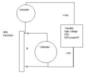
Thanks for your help guys. But one thing is the attached circuit the proper way of doing it? In case its not can you please correct it.
About your HT supply Andy do you have any means of controlling the voltage? Is that needed am a bit lost.
Anyway i've already purchased transformers to go the ESP way it will need a voltage doubler in the rectification. Got a 2SC3038 handy could use for CCS or varying voltage. It lest the HT PSU would be the ESP one but am going for the CCs method. Any diagram would be of great help thanks
Attachments
Andy L. Francis said:I did the same with many 2N3055s, I was asked to select them for ~100V Vceo.
I'll bet an awful lot of those Moto 'house #' devices used in all the 50 or so watt receivers of the 70's and 80's were just selected 2N3055's. It's really the right device to use on 80V rails if you just get past that 60V VCEO rating. Most any made today take 120+. Didn't one of the popular Dynaco amps use selected 2N3772's? I guess they were too cheap to spring for the 73's.
zeus_threat said:Thanks for your help guys. But one thing is the attached circuit the proper way of doing it? In case its not can you please correct it.
About your HT supply Andy do you have any means of controlling the voltage? Is that needed am a bit lost.
That is correct. Confused me for a minute putting the DUT in the emitter ckt, but as long as they're in series it's right. Just be careful you don't go testing the VCEO of your fingers.
You don't need to control the voltage on the HT supply. The current source will drop to the VCEO automatically. Read it on your DMM in parallel with the DUT. Just don't go using the DUT right up to the voltage you measure - as at that point it's leaking but the amount of the CCS, and if you apply one miserable volt more with no limiting you'll let the smoke out.
If you test your devices (140V rated) on this, you will likely measure 200-220 volts VCEO.
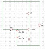
Is this better?
Thanks is the attached circuit better? Am confused where should i connect R2 in the figure to +ve or -ve supply line?
For my HT supply this is how i will set it up:
Transformer1 12V5A secondary into a second transformer secondary 12V and 0V(12-0-12V 2A) to obtain about 220V in second transformer primary, rectify with 4X1n4007smoothed with 100uF400V like Andy. Will that be enough?
Would the 2SC3038 need a huge heatsink+fan??
Thanks
P:S of course in an amp i can't use the transistor up to the measured VCE but still i'll have an idea of what i can take
Attachments
- Status
- This old topic is closed. If you want to reopen this topic, contact a moderator using the "Report Post" button.
- Home
- Amplifiers
- Solid State
- 100W peak 4Ohm