Another question what fuse rating would be recommended?
Would 6.3A slow blow be ok or too much? According to what i calculated peak current would be ~5.6 A
And completely different how much could i expect as RMS and peak power by bridging a pair of these amps into an 8ohm load?
Around 160?
Thanks
Would 6.3A slow blow be ok or too much? According to what i calculated peak current would be ~5.6 A
And completely different how much could i expect as RMS and peak power by bridging a pair of these amps into an 8ohm load?
Around 160?
Thanks
Hi Zeus,
read up on IV protection.
You are missing components for effective two slope locus.
You are also limiting DC output currents at the same level as non-damaging transient currents.
This will trigger on fast high level transients and sound terrible.
If your maximum continuous output current is 5.6A then use F3A in each supply rail after the main smoothing caps.
Sry Zeus Threat, many comments again.
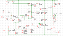
Warning, in the updated schematic the resistor values in the Vbe multiplier circuit are wrong!
I'd suggest the following values: R8: 1 kOhm; R17: 220..270 Ohm; VR1: 500 Ohm (470 Ohm).
As rail fuses I'd suggest 3.15A-F (fast-blow) as Andrew did.
RMS power of a bridged pair at 8 Ohm speaker impedance would be ~120W.
I remember that you decided for 3 pairs of output devices. But the third pair is unnecessary! For this 60W-RMS / 4 Ohm design the two pair of TIP2955/3055 is completely enough.
About drivers: my answer is OK. BD139/140's SOA is sufficient (I did a fast calculation). Then I'd replace all TIP41C/42C with BD139/140.
D5/D6 need to be fast diodes. Use 1N4148 there. But as D1/D4 1N4003 would be strong enough - no need for these 3A/200Ap rated 1N540X diodes.
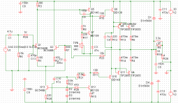
Sorry andrew but simulation is indicating that 1.5K is required for R8.
Wow that's strange! How does your simulator (Simetrix) indicating that?
 since design is complete. I'll post the pcb as soon as i get it done in eagle
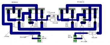
different PCB design
Well after lots of struggle with eagle for hours i came up to something acxtually i wanted the TIPs to be all in one line so that they could fit on an aluminium bracket then onto heatsink. So i could:
1) Hard wire the outputs as in M250
2) make a rectangular pcb as ESP subwoofer amp with the TIPS in two rows but then i would need to use wires to connect the TIPs in one row
3) Make 2 boards one with the circuit up to the drivers a second one with only the TIPs and the emitter resistors on a second one and run wires up there.
I prefer the third solution considering the limitations of eagle free version.
Hi Zeus
Question...Is your intent to have your PCB manufactured at a board house or to make it yourself? Two PCB's may cost more than one to have manufactured. I find the limitations of the freeware Eagle program to not be that bad, you should have plenty of room to draw everything you need on 1 PCB. I also like the 'bracket' idea.
This crazy circuit is in progress of creation in freeware Eagle. The outputs (TO-220 or TO-3P) will mount to the bracket, that will mount to the heatsink. The small SOT-23's drawn under the outputs are the Vbe multipliers, they will be in contact to the drain(collector if it was BJT) pin to sense the temperature. Also it is best to have the decoupling cap as close as possible to the corresponding output transistor. PCB design is an art form that requires experience. I'm certainly not an expert, but I'm learning....I think....
Totally agree CBS, actually am building my own pcb but to have the BJT, emitter resistors, fuse holder, plus 2 16mm caps placed in that tiny space is a real challenge with single sided PCB. I'll try to send the VBE multiplier through pcb lines to the BCE of BD am using in case its not possible i'll run wires for it and hook it up to the first npn output.
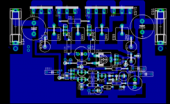
PCB V1.0
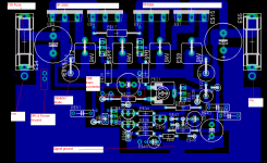
Hi attached is first pcb please do provide comments all are welcome. Thanks.
P:S:-I know stargrounding is the way to go but i've had much greater success with "flood grounding" using large copper area for power ground. Result is no hiss no noise no hum
Hi attached is first pcb please do provide comments all are welcome. Thanks.
P:S:-I know stargrounding is the way to go but i've had much greater success with "flood grounding" using large copper area for power ground. Result is no hiss no noise no hum
Attachments
hi zeus_threat,
You should really do your schematic with eagle then generate the PCB. The schematic defines the connectivity between components and virtually guarantees the PCB is correct.
It is very difficult for anyone but yourself to check your PCB without component numbering (that matches your schematic).
So...start again.
regards
Thanks for the advice but sorry won't have time. Guess should have labelled it a bit. For Q7 there are 3 via's to connect it to by wire. Actually i wanted to have an idea if the overall layout was ok meaning voltage section, power section and ground basically. There are a number of ways you can place an amp on a pcb but some will yield better peformance/ more stability than others.
- Status
- This old topic is closed. If you want to reopen this topic, contact a moderator using the "Report Post" button.
- Home
- Amplifiers
- Solid State
- 100W peak 4Ohm