Hi Damir,
The 100W CFA bom => "R37 560R 8W (four 560R 2W 1% metal film in parallel)"
Just clarifying this. Is this 4x560R resistors in parallel (effective paralleled resistance of 140R), or 4x resistors with an effective paralleled resistance of 560R, that can dissipate 8W?
The 100W CFA bom => "R37 560R 8W (four 560R 2W 1% metal film in parallel)"
Just clarifying this. Is this 4x560R resistors in parallel (effective paralleled resistance of 140R), or 4x resistors with an effective paralleled resistance of 560R, that can dissipate 8W?
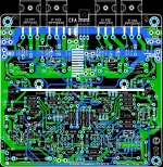
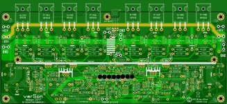
It should be 560R 8W, and it is done with two 560R 2W in parallel and then in series with other two 560R 2W in parallel all showed in the layout.Hi Damir,
The 100W CFA bom => "R37 560R 8W (four 560R 2W 1% metal film in parallel)"
Just clarifying this. Is this 4x560R resistors in parallel (effective paralleled resistance of 140R), or 4x resistors with an effective paralleled resistance of 560R, that can dissipate 8W?
Attachments

100W CFA uses +-50V and those mosfets Vds is 100V, on the brink of used voltage. I never used those, and can't recommend it.Can i use irfp 140 and 9140 for CFA 100W ?
I am coming back to my house next week and I will check that.Starting build up again of the CFA200 watt version. Damir do you have most recent fixes update in one ZIP file ?
It passed quite time from last changes of that amp. Could you be more specific what part is important for you, what PCB revision you use, unbalanced or balanced input version and so on?Any update here ?
BR Damir
I looked at a circuit variant with an additional pair of output mosfets (see attachment).
A very good driver (except for connecting the collectors of the input transistors) and a correctly applied Hauksford multiplier. you can safely connect a volume control potentiometer to the input of such a voltage amplifier, because. current tracking control is implemented in the input part of the circuit.
, but it’s not logical to parallel the driver for mosfets. in this case, the driver stage distortions add up because there is no additional reduction in output resistance to drive the mosfet gates.
Attachments
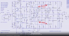
Could you elaborate about drivers?I looked at a circuit variant with an additional pair of output mosfets (see attachment).
A very good driver (except for connecting the collectors of the input transistors) and a correctly applied Hauksford multiplier. you can safely connect a volume control potentiometer to the input of such a voltage amplifier, because. current tracking control is implemented in the input part of the circuit.
, but it’s not logical to parallel the driver for mosfets. in this case, the driver stage distortions add up because there is no additional reduction in output resistance to drive the mosfet gates.
Could you elaborate about drivers?
Q11Q12 voltage amplifier input driver or Q6Q7 Q9Q10 mosfet driver?
Q11Q12 voltage amplifier input driver or Q6Q7 Q9Q10 mosfet driver?
Your coment “ but it’s not logical to parallel the driver for mosfets. in this case, the driver stage distortions add up because there is no additional reduction in output resistance to drive the mosfet gates.”
I used fast drivers to get more FB roomat higher frequencies, but those drivers are of low power and do not well drive four pairs od output mosfets.
Regarding input transistor collectors connected together, this work good as classical diamond connection.
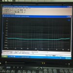
This amp was built some years ago in Thailand and with very low distortion, attached below.
Attachments

improve the control of 4 output mosfets, they should be paralleled to their gates, and not divided into two parallel pairs.I used fast drivers to get more FB roomat higher frequencies, but those drivers are of low power and do not well drive four pairs od output mosfets.
in the classic version of the diamond assembly, the collector of the first transistor is connected to a low-resistance point in order to reduce the influence of the input capacitance of Miller for increase the speed of the stage. In your case, it is really better to check on the model in which version this speed will be maximum.Regarding input transistor collectors connected together, this work good as classical diamond connection.
certainly good indicators, but even such indicators do not interfere with raising the technological level of the scheme even higher.This amp was built some years ago in Thailand and with very low distortion, attached below.
In my opinion transistors I used for the drivers can't drive four power mosfet pairs input capacitance, and higher power drivers like MJE15032/15033 are much slower and could not achieve enaufg NFB at 20kHzimprove the control of 4 output mosfets, they should be paralleled to their gates, and not divided into two parallel pairs.
Agree, later I switched back to classic diamond, but there is insignificant differencein the classic version of the diamond assembly, the collector of the first transistor is connected to a low-resistance point in order to reduce the influence of the input capacitance of Miller for increase the speed of the stage. In your case, it is really better to check on the model in which version this speed will be maximum.
certainly good indicators, but even such indicators do not interfere with raising the technological level of the scheme even higher.
you didn't understand my post.In my opinion transistors I used for the drivers can't drive four power mosfet pairs input capacitance, and higher power drivers like MJE15032/15033 are much slower and could not achieve enaufg NFB at 20kHz
I meant that to drive 4 pairs of mosfets, 2 pairs of driver transistors are needed, which should not be divided into pairs of mosfets.
it will depend on the type of correction, more precisely on the value of the depth of negative feedback at a frequency of 20 kHz. Now you can't see the difference due to high-speed current feedback, but miller correction has been introduced.Agree, later I switched back to classic diamond, but there is insignificant difference
You did not say that in post 1,612, not clearly at least.you didn't understand my post.
I meant that to drive 4 pairs of mosfets, 2 pairs of driver transistors are needed, which should not be divided into pairs of mosfets.
, but it’s not logical to parallel the driver for mosfets. in this case, the driver stage distortions add up because there is no additional reduction in output resistance to drive the mosfet gates.
Paralleling driver transistor with different beta, is this goos idea?
This amp is on the web quite long time and nobody said what you say here.
I will simulate it, could you point to what to take attention?
- Home
- Amplifiers
- Solid State
- 200W MOSFET CFA amp