Hi Dadod,
I was able to complete soldering the OPS components today, including drilling and tapping the heatsink. That took some amount of time to get it done.
Hi Fred,
1. "Powered up and did the VAS measurement, (R14 - R52) started at .525 Vdc and keeps on rising till it reached .635 Vdc."
That gives 52mA to 65mA of VAS current and that is not good. I hope that your measurement is wrong (probably 0.0525V). Don't change R14 and R52, measure voltage drop R5, it should show 1.3ma to 1.4mA of a current.
2. "I also tried to set the transistor bias to .03 V or 130 mA but after a while it start to drop. What is the proper way of adjusting the bias?"
Thermal compensation of this amp is a bit overcompensated (just in case no to go in thermal runaway). Correct the bias current after some thermal stabilization.
3. "Maybe this is the effect of using BC559 instead BC560?"
It should not influence it, but I hope that you use a pairs BC549/559?
4. "The DC offset goes up and down 8.3mv to 15mv without the op amp. With op amp installed, -2.5mv to 6.7mv. Is the fluctuation on the DC offset normal on this amp? "
If you've got so good result of DC offset before the op amp inserted ir's strange to fluctuate it so much after the op amp was inserted, check that is all according to BOM.
BR Damir
Hi Dadod,
1. "Powered up and did the VAS measurement, (R14 - R52) started at .525 Vdc and keeps on rising till it reached .635 Vdc."
That gives 52mA to 65mA of VAS current and that is not good. I hope that your measurement is wrong (probably 0.0525V). Don't change R14 and R52, measure voltage drop R5, it should show 1.3ma to 1.4mA of a current.
Based on your assembling instruction on post #911. Current reading thru R14 & R52 should be between 4 - 8 mA. Which is V= .004 x 100 = 0.4Vdc, correct me if I'm wrong. Mine reads V = .635 Vdc which quite high. The R5 & R6 was 1.79 to 1.815 Vdc.
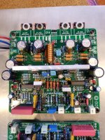
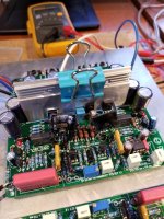
I just realize right now that you just change this settings to 1.3 to 1.4 mA instead of 1.4 to 1.5 mA. I don't know why I didn't think about this when I read your response this morning before working on the amp. But anyways, I increased R4 and R7, 909 and 887. I got 1.65 Vdc on R4 and R7 and .477 Vdc / 4.77mA on R14. I should have stayed on this setting. The Q6 and Q8 stayed cool. I thought 1.65 Vdc wasn't enough, So I change R4 and R7 again to 845 and 887. This settled to 1.73Vdc and R14 to .535 Vdc. Q6 and Q8 gets hot and also Q5 and Q7 heatsink. I double up the heatsink, see pic and also put heatsink on Q6, Q8. The temp on the VAS transistors settled to 46C. Monitored it for an hour and bias current stayed consistent from .535 to .540 Vdc.
I hope that you use a pairs BC549/559? Yes.
If you've got so good result of DC offset before the op amp inserted ir's strange to fluctuate it so much after the op amp was inserted, check that is all according to BOM.
I checked all parts on the board, compared to BOM and didn't find anything wrong. DC offset now is between -2mV to 3mV with Op amp installed.
I was really curious how the amp sounds, even though it was only mono, I hooked up my laptop headphone output directly to the amp. It sounds good. It will probably sounds better when both channels are working.
I think I still need to lower down the IPS bias next weekend. What you think Damir. Any thoughts?
BR Damir
Attachments
Sorry for wrong current calculation, it looks that my old brain stopped in that moment.
DC offset is OK. Just curious how good could be DC offset set with P2 (no op amp in the socket) and kipping R4 and R7 on the same value?
I hopped that it was good enough without changing values of R4 and R7.
Damir
Whats the difference between BC560CG and BC560CTA? I found some of these and will try to match with BC550CG. Any thoughts?
Nothing to do with the electrical characteristics, just different lead shape.
Thanks guys for your response. I would give it a shot. I will do some experiment, this might give me a better performance . Also thinking of using the BC557/547 which I have some of those too, but also now obsolete.
I came across the thread by Bonsai posted many years ago and he's using BC557/547, BC560/550 on his 100W CFA. Schematic wasn't posted there but on his website. http://hifisonix.com/wordpress/wp-content/uploads/2020/02/The-Ovation-nx-Amplifier-V2.10.pdf
I came across the thread by Bonsai posted many years ago and he's using BC557/547, BC560/550 on his 100W CFA. Schematic wasn't posted there but on his website. http://hifisonix.com/wordpress/wp-content/uploads/2020/02/The-Ovation-nx-Amplifier-V2.10.pdf
Thanks guys for your response. I would give it a shot. I will do some experiment, this might give me a better performance . Also thinking of using the BC557/547 which I have some of those too, but also now obsolete.
I came across the thread by Bonsai posted many years ago and he's using BC557/547, BC560/550 on his 100W CFA. Schematic wasn't posted there but on his website. http://hifisonix.com/wordpress/wp-content/uploads/2020/02/The-Ovation-nx-Amplifier-V2.10.pdf
You can use BC327-40/BC337-40.
Hi Damir
i had difficulties in BC560C(obsolete) and trafo (Talema from TME) because COVID 19.
Finally i use a mix of CDIL,ON and Philips.The problem now is C6 and C9 for which you suggest 270pF.What is better 220pF or 270pF?
regards
Andreas
Hi Andreas,
I suppose you mean instead of 250 pF for C6 and C9.
You can use 270 pF.
BR Damir
Hi Guys,
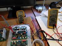
I got the time to play around again with my 100 CFA, just one channel. I lowered down the IPS bias to 1.62Vdc or 1.35mA, using 1K and 845 ohms on R4 and R7, thinking that it will lower down the current on R14 and R52 to 4.0mA. And I thought that it will lower down also temperature or the heat on Q5,Q6, Q7 and Q8, which on my previous post the temp of the transistors was hot. This time DC Offset is 12mV to18mV without opAmp. With OpAmp installed, -1mV to 3mV.
On the power up, (cold start) the voltage on R5 is 1.56Vdc and start to go to 1.62Vdc after 10 minutes. Same with the R14, voltage start at .343Vdc and goes up to .440Vdc. I was also observing the temperature of the heatsink at the same time of Q5 and Q7, as well as Q6 and Q8. After an hour, temperature rising to 47 to 48 degC. It seems like not normal to me. Is your amplifier doing the same?
I thought once the current is set, it should stay the same all the time. When I blow air to the heatsink of Q5 and Q7, the voltage at R14 drops to .368Vdc. I know that my heatsink on Q5 and Q7 is more than enough as on previous post.
I was able to play music and Im impress with sound quality of this amp. I just can't trust it right now. Then I have a disaster happened. When I was, measuring the voltage on R5, my test lead slip and shorted the zener diode D15. It pop and that's how my day end. I still have the other channel to play around.
Give me some feedback or any thoughts. Thanks.
Hi Guys,
I got the time to play around again with my 100 CFA, just one channel. I lowered down the IPS bias to 1.62Vdc or 1.35mA, using 1K and 845 ohms on R4 and R7, thinking that it will lower down the current on R14 and R52 to 4.0mA. And I thought that it will lower down also temperature or the heat on Q5,Q6, Q7 and Q8, which on my previous post the temp of the transistors was hot. This time DC Offset is 12mV to18mV without opAmp. With OpAmp installed, -1mV to 3mV.
On the power up, (cold start) the voltage on R5 is 1.56Vdc and start to go to 1.62Vdc after 10 minutes. Same with the R14, voltage start at .343Vdc and goes up to .440Vdc. I was also observing the temperature of the heatsink at the same time of Q5 and Q7, as well as Q6 and Q8. After an hour, temperature rising to 47 to 48 degC. It seems like not normal to me. Is your amplifier doing the same?
I thought once the current is set, it should stay the same all the time. When I blow air to the heatsink of Q5 and Q7, the voltage at R14 drops to .368Vdc. I know that my heatsink on Q5 and Q7 is more than enough as on previous post.
I was able to play music and Im impress with sound quality of this amp. I just can't trust it right now. Then I have a disaster happened. When I was, measuring the voltage on R5, my test lead slip and shorted the zener diode D15. It pop and that's how my day end. I still have the other channel to play around.
Give me some feedback or any thoughts. Thanks.
Fred, it sims that VAS currents is OK, about 4.4 mA after some time. I don't know what you used for drivers heat sink, but 48 degC is not to high. Just in case check the value of R17, if incidentally is to low (it should be 470R) drivers will dissipate more and heat more.
If you blow air to the drivers heatsink that will change the bias setting as a half of the bias spreader is fixed to that heat sink.
I think that you worry to much.
Damir
Hi Dadod
have you plan about SSR?Can you post the schematic?
Regards
Andreas, you can find the SSR schematic here. https://www.diyaudio.com/forums/solid-state/355093-ssr-power-amps.html#post6219435
Damir
Here is the last 200W-CFA-VMOSFET zip file with .asc and models files.
Damir
Hi Damir,
Please excuse my ignorance.
Your '200W-VMOSFET-efVAS-mc-RC-150-0_47u-OIC-DCservo- VDMOS ksubthres models-Vbe_blue.asc', has source resistors of different values. The IRFP240Ckst have 0.165R and the IRFP9240Cks 0.235R.
Can you let me know why they are different values please?
Hi Damir,
Please excuse my ignorance.
Your '200W-VMOSFET-efVAS-mc-RC-150-0_47u-OIC-DCservo- VDMOS ksubthres models-Vbe_blue.asc', has source resistors of different values. The IRFP240Ckst have 0.165R and the IRFP9240Cks 0.235R.
Can you let me know why they are different values please?
To compensate differences in not ideal complementary mosfets.
Thanks Damir,
I thought that might be the case as the datasheets show so many differences between the two.
Which of the parameters was the determining factor for the use of different values for the source resistor?
To my uneducated eye this would be for example the maximum Continuous Drain Current, Qg, Qgs or Forward Transconductance.
- Home
- Amplifiers
- Solid State
- 200W MOSFET CFA amp