I have just one 1.3.2b board left, and sorry but no gerbers for small board.If you are willing to share with a US based board house I'd get some built. how many 1.3.2b boards do you have left BTW if any ?
How many would you need?
I can order in steps of 5 boards. I can order 10 boards and send you 6 boards with price of 9 EUR per board plus shipping.Small boards I'd need 6 to go along with the 6 amp boards.
Let me know.
I'm fine with that Damir, if you can do it you can order 5 200watt CFA boards and then I'll take all 10 balanced boards along with 10 updated version 1.4 regulator boards and 5 200watt CFA boards.
Building the ultimate surround system. I would like a 12v trigger as well as SSR speaker protection if possible. Again not sure what you are willing to offer but if you are willing to offer all this I'll take it.
Building the ultimate surround system. I would like a 12v trigger as well as SSR speaker protection if possible. Again not sure what you are willing to offer but if you are willing to offer all this I'll take it.
"Building the ultimate surround system" it's very interesting.I'm fine with that Damir, if you can do it you can order 5 200watt CFA boards and then I'll take all 10 balanced boards along with 10 updated version 1.4 regulator boards and 5 200watt CFA boards.
Building the ultimate surround system. I would like a 12v trigger as well as SSR speaker protection if possible. Again not sure what you are willing to offer but if you are willing to offer all this I'll take it.
It was quite time ago and I have to check all that what said. I don't remember 1.4 regulator board, could you point more precisely?
I am interested to do all what you mentioned but I need time to recheck all that.
BR Damir
The regulator board I've got is version 1.2 however I believe there is now a 1.4 revision at least for the 100W design perhaps the 200 watt did not change.
https://flic.kr/p/2nUpVFn
https://flic.kr/p/2nUpVFn
I sent you PM with proposal for the boards.The regulator board I've got is version 1.2 however I believe there is now a 1.4 revision at least for the 100W design perhaps the 200 watt did not change.
https://flic.kr/p/2nUpVFn
Damir
what is the optimal quiescent current?I would like to offer gerbers for my 100W CFA and corresponding Power Supply.
I hope more people will build this amp.")
Hi Theo,Damir,
Also wondering where you source your 2W metal film resistors for .33 and .47 resistors as part of the BOM ... only ones I can find from mouser or digikey are Vishay and are like 3 bucks each ... little too pricey.
I bought them on Ebay, metal film type, even carbon film could do.
Damir
Few questions looking at the balanced board version 1.2 BOM ... the board looks different then the the one in your build instructions, posted in this thread which I take it is the original version. You have In and out on this board as well as S3 terminal block? Want to make sure I understand the connections to the main board clearly.
Also U1, M1, M2 are not specified in the BOM do these need to be populated ?
I take it C3 and C4 are 1uF ceramic caps ?
Confirm S1 and S2 are Red LEDs.
C7 is also missing from the BOM version 1.2.
Also U1, M1, M2 are not specified in the BOM do these need to be populated ?
I take it C3 and C4 are 1uF ceramic caps ?
Confirm S1 and S2 are Red LEDs.
C7 is also missing from the BOM version 1.2.
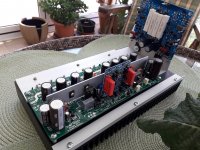
Attachments
Thanks Damir I will ignore those parts on the regulator as you suggest.
Another question on the regulator ...
R32 and R33 would seem too short at 15mm pitch for lead spacing to accommodate a 4.7K 5W wirewound resistor ... would need guidance on this part.
I was able to find a vishay wirewound that is slightly too big at 18mm that I could make work. Is there a specific resistor you had in mind for R32 / R33?
My last question on the voltage reg would be R9 and R109 you list .15R but do you mean a total of 10W in parallel meaning two 5 watt rated resistors or two 10W rated resistors ?
R32 and R33 are not critical, each one dissipate around 1W and there here to discharge the power supplay big caps in case of failer when the PS regulator was triggered off. In this case you need to switch the power off and wait that PS regulator resets.
You can go wthout those resistor and in this case the reset time is going to be longer. You can use here 2W or 3W resistor that is good enough.
Yes you need two 0.15R 10W resistors in parallel for R9 and R10, in total 0.075R 20W. That is where overcurrent protection sensed.
You can go wthout those resistor and in this case the reset time is going to be longer. You can use here 2W or 3W resistor that is good enough.
Yes you need two 0.15R 10W resistors in parallel for R9 and R10, in total 0.075R 20W. That is where overcurrent protection sensed.
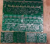
I still have two sets of the PCBs for 200W CFA balanced amplifiear and SSR DCoffset protection.
Price 200 EUR plus shipping for one set of the boards (two main amplifier boards, two addon balanced boards and two SSR boards).
Damir
Link to SSR thread: https://www.diyaudio.com/community/threads/ssr-for-power-amps.355093/
Price 200 EUR plus shipping for one set of the boards (two main amplifier boards, two addon balanced boards and two SSR boards).
Damir
Link to SSR thread: https://www.diyaudio.com/community/threads/ssr-for-power-amps.355093/
Attachments
Last edited:
- Home
- Amplifiers
- Solid State
- 200W MOSFET CFA amp