I don't know that the Ayumi models in general are based on any particular manufacturer's tube data. But I've found the Ayumi models to be good enough for basic simulation, with the usual caveat that SPICE models are not perfect so there is no substitute for bench testing.
Hi RayI don't know that the Ayumi models in general are based on any particular manufacturer's tube data. But I've found the Ayumi models to be good enough for basic simulation, with the usual caveat that SPICE models are not perfect so there is no substitute for bench testing.
For me, the Ayumi models are a class of its own. The achieved accuracy level is remarkable when we consider, that he uses only 4 (!!) parameters (sometimes 6) for a triode model including a grid model. For many needs, they are good enough.
But more accurate models shift the point where bench tests has to start, e.g:
- simulation of THD, as Koonw demonstrated in his last post
- bias setting with grid resistor instead of cathode resistor (often used for battery amps, in rare cases also in other stages e.g. #2382)
- simulation of small signal rectification effects, e.g. in audion radio stages
- investigations of clipping behavior, and how they shift bias points, and recovery of that mode
- listen how overdriven Guitaramps will sound, and what the influence of modifications is, with .WAV files.
cheers, Adrian
Hi Adrian, question for you regarding your last post.
I've used your 12AT7 i4 model and the Ayumi 12AT7 model, to compare.
Usually the Ayumi model predicts higher THD than your model does, as in the simulation I've attached to this post.
Does that mean I should trust THD predictions from your model more than I should those using the Ayumi model?
Or perhaps I'm not doing the THD modeling correctly...
Attachments
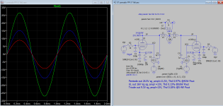
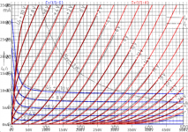
6N17B Curve Captor and Ayumi models.
6N17B Curve Captor and Ayumi models.
Curve Captor:
Ayumi model:
6N17B Curve Captor and Ayumi models.
Curve Captor:
Code:
* 6N17B LTSpice model
* Modified Koren model (8 parameters): mean fit error 0.0935463mA
* Traced by Wayne Clay on 10/10/2018 using Engauge Digitizer and
* Curve Captor v0.9.1 from Soviet data sheet
.subckt 6N17B  P G K
    Bp  P K  I=(8.881819189e-05m)*uramp(V(P,K)*ln(1.0+(-0.05787376447)+exp((0.7467399581)+(0.7467399581)*((266.0580109)+(3397.261292m)*V(G,K))*V(G,K)/sqrt((-0.6714542748)**2+(V(P,K)-(-63.58379404))**2)))/(0.7467399581))**(2.021894)
    Cgp G P  1.8p ; 0.2p added (1.6p)
    Cgk G K  3.6p ; 0.7p added (2.9p)
    Cpk P K  1.9p ; 0.2p added (1.7p)
    Rpk P K  1G ; to avoid floating nodes
    d3  G K  dx1
.model dx1 d(is=1n rs=2k cjo=1pf N=1.5 tt=1n)
.ends 6N17B
Code:
*
* Generic triode model: 6N17B_AN
* Copyright 2003--2008 by Ayumi Nakabayashi, All rights reserved.
* Version 3.10, Generated on Fri Oct 12 14:46:37 2018
*                Plate
*                | Grid
*                | | Cathode
*                | | |
.SUBCKT 6N17B_AN A G K
BGG   GG   0 V=V(G,K)+-0.35544294
BM1   M1   0 V=(0.01291172*(URAMP(V(A,K))+1e-10))**-2.0483062
BM2   M2   0 V=(0.42273692*(URAMP(V(GG)+URAMP(V(A,K))/44.708457)+1e-10))**3.5483062
BP    P    0 V=0.0043126487*(URAMP(V(GG)+URAMP(V(A,K))/105.75953)+1e-10)**1.5
BIK   IK   0 V=U(V(GG))*V(P)+(1-U(V(GG)))*0.0081637051*V(M1)*V(M2)
BIG   IG   0 V=0.0021563244*URAMP(V(G,K))**1.5*(URAMP(V(G,K))/(URAMP(V(A,K))+URAMP(V(G,K)))*1.2+0.4)
BIAK  A    K I=URAMP(V(IK,IG)-URAMP(V(IK,IG)-(0.0022176355*URAMP(V(A,K))**1.5)))+1e-10*V(A,K)
BIGK  G    K I=V(IG)
* CAPS
CGA   G    A 1.6p
CGK   G    K 2.9p
CAK   A    K 1.7p
.ENDS
Attachments
Yes they are. Listed in the upper left panel under "remark".I don't know that the Ayumi models in general are based on any particular manufacturer's tube data.
Attachments
Good to know -- thanks. But Ayumi doesn't routinely include this information in the actual model files he publishes. Here is the 6CG7 model as an example:
Code:
*
* Generic triode model: 6CG7
* Copyright 2003--2008 by Ayumi Nakabayashi, All rights reserved.
* Version 3.10, Generated on Sat Mar  8 22:39:40 2008
*            Plate
*            | Grid
*            | | Cathode
*            | | |
.SUBCKT 6CG7 A G K
BGG   GG   0 V=V(G,K)+0.54900933
BM1   M1   0 V=(0.020494606*(URAMP(V(A,K))+1e-10))**-0.76277031
BM2   M2   0 V=(0.66290422*(URAMP(V(GG)+URAMP(V(A,K))/16.448024)+1e-10))**2.2627703
BP    P    0 V=0.0012465111*(URAMP(V(GG)+URAMP(V(A,K))/24.812067)+1e-10)**1.5
BIK   IK   0 V=U(V(GG))*V(P)+(1-U(V(GG)))*0.00074417047*V(M1)*V(M2)
BIG   IG   0 V=0.0003834058*URAMP(V(G,K))**1.5*(URAMP(V(G,K))/(URAMP(V(A,K))+URAMP(V(G,K)))*1.2+0.4)
BIAK  A    K I=URAMP(V(IK,IG)-URAMP(V(IK,IG)-(0.0006816103*URAMP(V(A,K))**1.5)))+1e-10*V(A,K)
BIGK  G    K I=V(IG)
* CAPS
CGA   G    A 4p
CGK   G    K 2.3p
CAK   A    K 2.2p
.ENDS@Adrian,
I have gotten good results with the Ayumi models and will usually start a simulation with them but if something looks a bit off I will try other models. I typically only design with tubes that are in current production so multiple models are available for most of the tubes that I use regularly.
I've been following your own modeling project and would like to try some but as of last week I didn't find models for some of the tubes I use. Boring as it is, the tube families I like are all of the 12A?7 tubes and variants, the 6SN7/6CG7, the ECC88/6922/6N23P family, and the common output tubes: EL84, EL34, 6550/KT88, and similar. You have provided models for some of the 12A?7 tubes but are any of the others planned for future addition to your library?
I don't blame you for not going to the trouble of editing the output files. And although that is useful information, my design goals include being somewhat brand-agnostic. Hopefully, most 6CG7s, for example, will have characteristics similar enough to the GE tube model that it won't matter all that much as far as circuit performance goes.
Some day I'll get around to learning how to create my own model files instead of relying on the helpful people in this forum. I have a bunch of your models in my library.")
Some day I'll get around to learning how to create my own model files instead of relying on the helpful people in this forum. I have a bunch of your models in my library.
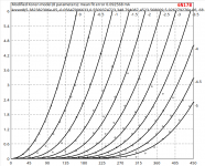
The valves (toobs) I'd like for Adrian to tackle would be the high transconductance frame grid types such as: 6GK5, 6HA5, 6HM5, 6HQ5... etc. Trying to accurately model those with Curve Captor and the Ayumi method is an act of futility. The Ayumi method does better, but the 0Vg and the -1Vg curves are way off. Of course that is with the published curves. The 5751 would be nice also.
I'd love to request a model for the 12CA5 as both a pentode and as a triode if possible. Thank you!
Edit - Actually I'm going to turn this into a much larger request because I keep searching and coming up empty. I guess I want to use unusual tubes!
Full List of Tubes of Interest
12CA5 (or 6CA5)
12FX5
6E5P
6J22P
6J52P
6P9
Edit - Actually I'm going to turn this into a much larger request because I keep searching and coming up empty. I guess I want to use unusual tubes!
Full List of Tubes of Interest
12CA5 (or 6CA5)
12FX5
6E5P
6J22P
6J52P
6P9
Last edited:
Re: RF frame grid triodes (6HA5, 6HQ5, 6HM5, etc.):
That would be awesome! There is a data sheet for 6HQ5 that has plate curves. Most of these triodes' data sheets don't have curves.
I'll add PC900, EC97, 6FY5 to the list.
Re: 12CA5:
I think 12CA5 is pretty much the same thing as 12C5. If so, there is an Ayumi model for that.
Pentode:
Triode:
Ale Moglia published a 6J52P triode model:
I also have a 6J9P model in my collection (I don't remember where I found it):
Ale also made a 6e5P triode model:
--
That would be awesome! There is a data sheet for 6HQ5 that has plate curves. Most of these triodes' data sheets don't have curves.
I'll add PC900, EC97, 6FY5 to the list.
Re: 12CA5:
I think 12CA5 is pretty much the same thing as 12C5. If so, there is an Ayumi model for that.
Pentode:
Code:
* Generic pentode model: 12C5_AN
* Copyright 2003--2008 by Ayumi Nakabayashi, All rights reserved.
* Version 3.10, Generated on Mon May 12 19:52:23 2014
*               Plate
*               |  Screen Grid
*               |  |  Control Grid
*               |  |  | Cathode
*               |  |  | |
.SUBCKT 12C5_AN A G2 G1 K
BGG   GG   0 V=V(G1,K)+0.64467779
BM1   M1   0 V=(0.075297466*(URAMP(V(G2,K))+1e-10))**-0.98308664
BM2   M2   0 V=(0.60408685*(URAMP(V(GG)+URAMP(V(G2,K))/5.2579876)))**2.4830866
BP    P    0 V=0.0030725552*(URAMP(V(GG)+URAMP(V(G2,K))/8.7040258))**1.5
BIK   IK   0 V=U(V(GG))*V(P)+(1-U(V(GG)))*0.0020281675*V(M1)*V(M2)
BIG   IG   0 V=0.0015362776*URAMP(V(G1,K))**1.5*(URAMP(V(G1,K))/(URAMP(V(A,K))+URAMP(V(G1,K)))*1.2+0.4)
BIK2  IK2  0 V=V(IK,IG)*(1-0.4*(EXP(-URAMP(V(A,K))/URAMP(V(G2,K))*15)-EXP(-15)))
BIG2T IG2T 0 V=V(IK2)*(0.947317212*(1-URAMP(V(A,K))/(URAMP(V(A,K))+10))**1.5+0.052682788)
BIK3  IK3  0 V=V(IK2)*(URAMP(V(A,K))+625)/(URAMP(V(G2,K))+625)
BIK4  IK4  0 V=V(IK3)-URAMP(V(IK3)-(0.0020807128*(URAMP(V(A,K))+URAMP(URAMP(V(G2,K))-URAMP(V(A,K))))**1.5))
BIP   IP   0 V=URAMP(V(IK4,IG2T)-URAMP(V(IK4,IG2T)-(0.0020807128*URAMP(V(A,K))**1.5)))
BIAK  A    K I=V(IP)+1e-10*V(A,K)
BIG2  G2   K I=URAMP(V(IK4,IP))
BIGK  G1   K I=V(IG)
* CAPS
CGA   G1  A  0.64p
CGK   G1  K  7.8p
C12   G1  G2 5.2p
CAK   A   K  6.1p
.ENDS
Triode:
Code:
*
* Generic triode model: 12C5-Triode
* Copyright 2003--2008 by Ayumi Nakabayashi, All rights reserved.
* Version 3.10, Generated on Sat Mar  8 22:41:22 2008
*              Plate
*              | Grid
*              | | Cathode
*              | | |
.SUBCKT 12C5-T A G K
BGG   GG   0 V=V(G,K)+0.99999998
BM1   M1   0 V=(0.12544688*(URAMP(V(A,K))+1e-10))**-1.6161868
BM2   M2   0 V=(0.48135753*(URAMP(V(GG)+URAMP(V(A,K))/4.1343593)+1e-10))**3.1161868
BP    P    0 V=0.0021455369*(URAMP(V(GG)+URAMP(V(A,K))/8.5889574)+1e-10)**1.5
BIK   IK   0 V=U(V(GG))*V(P)+(1-U(V(GG)))*0.0024204769*V(M1)*V(M2)
BIG   IG   0 V=0.0010727685*URAMP(V(G,K))**1.5*(URAMP(V(G,K))/(URAMP(V(A,K))+URAMP(V(G,K)))*1.2+0.4)
BIAK  A    K I=URAMP(V(IK,IG)-URAMP(V(IK,IG)-(0.0014581748*URAMP(V(A,K))**1.5)))+1e-10*V(A,K)
BIGK  G    K I=V(IG)
* CAPS
CGA   G    A 5.2p
CGK   G    K 6.9p
CAK   A    K 8.4p
.ENDS
Ale Moglia published a 6J52P triode model:
Code:
**** 6Z52P TRIODE ******************************************
* Created on 11/17/2013 19:25 using paint_kit.jar Version 2.4 Beta. May 2013
* Curve traced and model by Ale Moglia 2013 [email]valves@bartola.co.uk[/email]
* Curves image file: 6Z52P TRIODE
* Data source link: [url=http://www.bartola.co.uk/valves]Bartola® Valves – All about electronic valves and hi-fi[/url]
*----------------------------------------------------------------------------------
.SUBCKT TRIODE_6Z52P 1 2 3 ; Plate Grid Cathode
+ PARAMS: CCG=13.5P CGP=0.5P CCP=2P RGI=2000
+ MU=76.5 KG1=34.7 KP=252 KVB=1272 VCT=-0.11 EX=1.39
* Vp_MAX=200 Ip_MAX=200 Vg_step=0.5 Vg_start=0 Vg_count=8
* Rp=4000 Vg_ac=55 P_max=11.2 Vg_qui=-48
* X_MIN=64 Y_MIN=48 X_SIZE=421 Y_SIZE=530 FSZ_X=995 FSZ_Y=675 XYGrid=false
*----------------------------------------------------------------------------------
E1 7 0 VALUE={V(1,3)/KP*LOG(1+EXP(KP*(1/MU+(VCT+V(2,3))/SQRT(KVB+V(1,3)*V(1,3)))))}
RE1 7 0 1G ; TO AVOID FLOATING NODES
G1 1 3 VALUE={(PWR(V(7),EX)+PWRS(V(7),EX))/KG1}
RCP 1 3 1G ; TO AVOID FLOATING NODES
C1 2 3 {CCG} ; CATHODE-GRID
C2 2 1 {CGP} ; GRID=PLATE
C3 1 3 {CCP} ; CATHODE-PLATE
D3 5 3 DX ; POSITIVE GRID CURRENT
R1 2 5 {RGI} ; POSITIVE GRID CURRENT
.MODEL DX D(IS=1N RS=1 CJO=10PF TT=1N)
.ENDS
*$
I also have a 6J9P model in my collection (I don't remember where I found it):
Code:
**** 6J9P_4 ******************************************
* Created on 11/25/2013 00:58 using paint_kit.jar 2.6
* Model Paint Tools: Trace Tube Parameters over Plate Curves, Interactively
* Plate Curves image file: 6j9p_4.jpg
* Data source link:
*----------------------------------------------------------------------------------

.SUBCKT 6J9P 1 4 2 3 ; P K G2 G1
+ PARAMS: CCG=8.5P CGP=0.03P CCP=3P RGI=2000
+ MU=55.9 KG1=280.9 KP=369.1 KVB=23.1 EX=1.49 KG2=400
* Vp_MAX=480 Ip_MAX=40 Vg_step=0.5 Vg_start=-0.5 Vg_count=5
* Rp=1600 Vg_ac=23.5 P_max=7.5 Vg_qui=-23.4 Vp_qui=240 UL=0.469 EG2=139.2
* X_MIN=73 Y_MIN=50 X_SIZE=365 Y_SIZE=256 FSZ_X=1032 FSZ_Y=742 XYGrid=false
* showLoadLine=n showIp=y isDHT=n isPP=n isAsymPP=n isUL=n showDissipLimit=n
* showIg1=y gridLevel2=n isInputSnapped=n
* XYProjections=n harmonicPlot=y harmonics=y
*----------------------------------------------------------------------------------
RE1 7 0 1MEG ; DUMMY SO NODE 7 HAS 2 CONNECTIONS
E1 7 0 VALUE= ; E1 BREAKS UP LONG EQUATION FOR G1.
+{V(4,3)/KP*LOG(1+EXP((1/MU+V(2,3)/V(4,3))*KP))}
G1 1 3 VALUE={(PWR(V(7),EX)+PWRS(V(7),EX))/KG1*ATAN(V(1,3)/KVB)}
G2 4 3 VALUE={(EXP(EX*(LOG((V(4,3)/MU)+V(2,3)))))/KG2}
RCP 1 3 1G ; FOR CONVERGENCE
C1 2 3 {CCG} ; CATHODE-GRID 1
C2 1 2 {CGP} ; GRID 1-PLATE
C3 1 3 {CCP} ; CATHODE-PLATE
R1 2 5 {RGI} ; FOR GRID CURRENT
D3 5 3 DX ; FOR GRID CURRENT
.MODEL DX D(IS=1N RS=1 CJO=10PF TT=1N)
.ENDS
Ale also made a 6e5P triode model:
Code:
* Created on Sun May 27 08:27:41 BST 2012 using tube.model.finder.PaintKIT
* model URL: [url=http://www.bartola.co.uk/valves]Bartola® Valves – All about electronic valves and hi-fi[/url]
*--------------------------------------------------
.SUBCKT 6E5P_TRIODE_AM 1 2 3 ; P G K ;
+ PARAMS: CCG=15P  CGP=0.6P CCP=2.5P RGI=2000
+ MU=32.175 EX=1.6568 KG1=162.5332 KP=272.1997 KVB=0.35 VCT=-0.695 ; Vp_MAX=250.0 Ip_MAX=0.08 Vg_step=0.5
*--------------------------------------------------
E1 7 0 VALUE={V(1,3)/KP*LOG(1+EXP(KP*(1/MU+(VCT+V(2,3))/SQRT(KVB+V(1,3)*V(1,3)))))}
RE1 7 0 1G
G1 1 3 VALUE={(PWR(V(7),EX)+PWRS(V(7),EX))/KG1}
RCP 1 3 1G   ; TO AVOID FLOATING NODES
C1 2 3 {CCG} ; CATHODE-GRID
C2 2 1 {CGP} ; GRID=PLATE
C3 1 3 {CCP} ; CATHODE-PLATE
D3 5 3 DX ; FOR GRID CURRENT
R1 2 5 {RGI} ; FOR GRID CURRENT
.MODEL DX D(IS=1N RS=1 CJO=10PF TT=1N)
.ENDS
*$
--
Last edited:
Thank you.
I'm a little leery of using the 12C5 model because I'm looking at simulating my oddball amp that currently has a B+ of 96V. Who knows if any model will be correct in that realm but I'd rather not start with one that matches a tube with roughly twice the rated output.
The triode models are great but I'd really love pentode models to go with PP topologies.
BTW, how well do pentode/tetrode models work if you triode strap them in the simulation? Is there really a need for separate triode models if you have the pentode ones?
Hi rongon,Hi Adrian, (...)
Does that mean I should trust THD predictions from your model more than I should those using the Ayumi model? (...)
For THD simulation, two tube effects/laws are essential:
- the exponent of Langmuir-Child's law, typically between 1.3 and 1.7
- the Island effect
Ayumis models are inflexible regarding the exponent (always 1.5).
Most accurate method to mimic the island effect of most triodes is Koren's approach, which is carried over in almost all triode model approaches (including mine) except Ayumi's and Rydel's (and some further rare approaches).
That's why I would not simulate THD with an Ayumi model as long as there is another model (with Koren based island effect and flexible exponent) available.
cheers, Adrian
Ray,@Adrian,
(...) Boring as it is, the tube families I like are all of the 12A?7 tubes and variants, the 6SN7/6CG7, the ECC88/6922/6N23P family, and the common output tubes: EL84, EL34, 6550/KT88, and similar. You have provided models for some of the 12A?7 tubes but are any of the others planned for future addition to your library?
I'm highly committed to continue creating tube spice models, but I have to fight with two "bottlenecks":
1) My spare time is quite limited (well, during holiday's, it's obviously better
)2) Money
Why Money?? Well, the story is like follows:
To achieve a certain gm & mu with a given heater power, several tube constructions are suitable. So, each tube company may have its own construction for a certain triode type like an ECC82 (long & short plate versions, strap grid versions etc.)
But grid current is another story - it is strongly construction dependent! (That's way I include 2 letters for the manufacturer in the model name since version i4, assuming that a manufacturer will not change it's construction without renaming the tube of concern)
As it is the claim of my models to be suitable for ALL KIND of simulations, grid current is an important topic for me. Many data sheets ignore that topic, so I have to get and measure it. I always measure several tubes, to avoid fitting my model on a "monday morning tube" with untypical curves. No problem for NOS soviet tubes, as they are super cheap
. For the not so cheap west tubes, different solutions are possible:- in best case, the data sheet contains sufficient grid data
- for the 12AT7 model, I got complete measurements done by the requester
- For my 12AX7 model, I got a parcel from a sound effect company with 5 tubes, measured them with my iTracer, and shipped them back.
- George (Tubelab_com) just shipped me some tubes for "spicing", without the need of shipping them back
That's why there is no plan for west tubes, but if there is an occasion, I will create a model. For NOS soviet tubes, I plan to do: 6N1P, 6N2P (6N3P already done) 6N15P, 6N16B, hope fully 6N17B-V (deal in progress)
cheers, Adrian
Last edited:
You can use a pentode model also in triode mode when the pentode model is able to deliver correct plate and g2 currents for ANY Vg2 (not just for ONE Vg2).BTW, how well do pentode/tetrode models work if you triode strap them in the simulation? Is there really a need for separate triode models if you have the pentode ones?
I'm not 100% sure, but I guess an Ayumi pentode model behaves so.
cheers, Adrian
Hi Ray(...) Boring as it is, the tube families I like are all of the 12A?7 tubes and variants (...)
There's an ECC82 triode model missed in my lib. So I had a closer look to frank's data sheet collection, whether there is a datasheet containing sufficient grid current curves. And there is!!
The Philips E82CC data sheet has really god grid data, so I created a model for you
.It is a long plate triode, hence also valid for Telefunken ECC82 and the like of same construction.
cheers, Adrian
Code:
*E82CC LTspice model based on the generic triode model from Adrian Immler, version i4
*A version log is at the end of this file
*Params fitted to Philips datasheet by Adrian Immler, Dec. 2020
*The high fit quality is presented at adrianimmler.simplesite.com
*History's best of tube decribing art (plus some new ideas) is merged to this new approach.
*@ neg. Vg, Ia accuracy is similar to Koren or Ayumi models.
*@ small neg. Vg, the "Anlauf" current is considered.
*@ pos. Vg, Ig and Ia accuracy is on a unrivaled level.
*This offers new simulation possibilities like bias point setting with MOhm grid resistor,
*Audion radio circuits, low voltage amps, guitar distortion stages or pulsed stages.
* anode (plate)
* | grid
* | | cathode
* | | |
.subckt E82CC.PHi4 A G K
.params
*Parameters for the space charge current @ Vg <= 0
+ mu = 20.22;Determines the voltage gain @ constant Ia
+ rad = 5k5 ;Differential anode resistance, set @ Iad and Vg=0V
+ Vct = 0.55 ;Offsets the Ia-traces on the Va axis. Electrode material's contact potential
+ kp = 75.9 ;Mimics the island effect
+ xs = 1.5 ;Determines the curve of the Ia traces. Typically between 1.2 and 1.8
*
*Parameters for assigning the space charge current to Ia and Ig @ Vg > 0
+ kB = 0.33 ;Describes how fast Ia drops to zero when Va approaches zero.
+ radl = 557 ;Differential resistance for the Ia emission limit @ very small Va and Vg > 0
+ tsh = 4 ;Ia transmission sharpness from 1th to 2nd Ia area. Keep between 3 and 20. Start with 20.
+ xl = 1.2 ;Exponent for the emission limit
*
*Parameters of the grid-cathode vacuum diode
+ kvdg = 100 ;virtual vacuumdiode. Causes an Ia reduction @ Ig > 0.
+ kg = 3k86 ;Inverse scaling factor for the Va independent part of Ig (caution - interacts with xg!)
+ Vctg = 0.5 ;Offsets the log Ig-traces on the Vg axis. Electrode material's contact potential
+ xg = 1.5 ;Determines the curve of the Ig slope versus (positive) Vg and Va >> 0
+ VT = 0.1 ;Log(Ig) slope @ Vg<0. VT=k/q*Tk (cathodes absolute temp, typically 1150K)
+ kVT=0 ;Va dependant koeff. of VT
+ Vft2 = 0 gft2 = 0 ;finetunes the gridcurrent @ low Va and Vg near zero
*
*Parameters for the caps
+ cag = 1p5 ;From datasheet
+ cak = 0p5 ;From datasheet
+ cgk = 1p6 ;From datasheet
*
*special purpose parameters
+ os = 1 ;Overall scaling factor, if a user wishes to simulate manufacturing tolerances
*
*Calculated parameters
+ Iad = 100/rad ;Ia where the anode a.c. resistance is set according to rad.
+ ks = pow(mu/(rad*xs*Iad**(1-1/xs)),-xs) ;Reduces the unwished xs influence to the Ia slope
+ ksnom = pow(mu/(rad*1.5*Iad**(1-1/1.5)),-1.5) ;Sub-equation for calculating Vg0
+ Vg0 = Vct + (Iad*ks)**(1/xs) - (Iad*ksnom)**(2/3) ;Reduces the xs influence to Vct.
+ kl = pow(1/(radl*xl*Ild**(1-1/xl)),-xl) ;Reduces the xl influence to the Ia slope @ small Va
+ Ild = sqrt(radl)*1m ;Current where the Il a.c. resistance is set according to radl.
*
*Space charge current model
Bggi GGi 0 V=v(Gi,K)+Vg0 ;Effective internal grid voltage.
Bahc Ahc 0 V=uramp(v(A,K)) ;Anode voltage, hard cut to zero @ neg. value
Bst St 0 V=uramp(max(v(GGi)+v(A,K)/(mu), v(A,K)/kp*ln(1+exp(kp*(1/mu+v(GGi)/(1+v(Ahc)))))));Steering volt.
Bs Ai K I=os/ks*pow(v(St),xs) ;Langmuir-Childs law for the space charge current Is
*
*Anode current limit @ small Va
.func smin(z,y,k) {pow(pow(z+1f, -k)+pow(y+1f, -k), -1/k)} ;Min-function with smooth trans.
Ra A Ai 1
Bgl Gi A I=min(i(Ra)-smin(1/kl*pow(v(Ahc),xl),i(Ra),tsh),i(Bgvd)*exp(4*v(G,K))) ;Ia emission limit
*
*Grid model
Bvdg G Gi I=1/kvdg*pwrs(v(G,Gi),1.5) ;Reduces the internal effective grid voltage when Ig rises
Rgip G Gi 1G ;avoids some warnings
Cvdg G Gi 0p1;this small cap improves convergence
.func fVT() {VT*exp(-kVT*sqrt(v(A,K)))}
.func Ivd(Vvd, kvd, xvd, VTvd) {if(Vvd < 3, 1/kvd*pow(VTvd*xvd*ln(1+exp(Vvd/VTvd/xvd)),xvd), 1/kvd*pow(Vvd, xvd))} ;Vacuum diode function
Bgvd Gi K I=Ivd(v(G,K) + Vctg, kg/os, xg, fVT())
.func ft2() {gft2*(1-tanh(3*(v(G,K)+Vft2)))} ;Finetuning-func. improves ig-fit @ Vg near -0.5V, low Va.
Bgr Gi Ai I=ivd(v(GGi),ks/os, xs, 1.1*VT)/(1+ft2()+kB*v(Ahc));Is reflection to grid when Va approaches zero
Bs0 Ai K I=ivd(v(GGi),ks/os, xs, 1.1*VT)/(1+ft2()) - os/ks*pow(v(GGi),xs) ;Compensates neg Ia @ small Va and Vg near zero
*
*Caps
C1 A G {cag}
C2 A K {cak}
C3 G K {cgk}
.end
*
*Version log
*i1 :Initial version
*i2 :Pin order changed to the more common order âA G Kâ (Thanks to Markus Gyger for his tip)
*i3 :bugfix of the Ivd-function: now also usable for larger Vvd
*i4: Rgi replaced by a virtual vacuum diode (better convergence). ft1 deleted (no longer needed)
;2 new prarams for Ig finetuning @ Va and Vg near zero. New emission skaling factor ke for aging etc.Attachments
- Home
- Amplifiers
- Tubes / Valves
- Vacuum Tube SPICE Models