Here you go Nigel, another free offering with quite a range of tones and some interesting optional test features that you can play directly as FLAC, APE or WAVPACK files or burn a CD if you prefer something in solid, 16 bit/44.1 format. It's also a UK product so I expect you would be able to get help if needed.
Test CD
Thanks Ian that is a great help. My stereo JLH failed. Too much of a birds nest. I am transfering it to vero-strip board. Should it work well I can post that.
Have used TO-3-brackets. For the active psu. Yesterday. Removed and direct contacted. Today. Now fluid, much more open, cleaner, clearer...-)
If you do use screws for current - TO-3-fixing -, use one metal and one plastic. You will get less noise, a bit finer sound. You will listen - you should;-)
If you do use screws for current - TO-3-fixing -, use one metal and one plastic. You will get less noise, a bit finer sound. You will listen - you should;-)
If they were I'd be in a better place. However some have labels like "Q4" without indication of what type it is or orientation.for the list part, all references are printed on the pcb
I now have a schema, it's pretty standard, there is also a PSU section based on a Darlington pair, I'll post it up.the diagram,
I'm a distance away from that yet, not yet got a parts list.for the setting, it's like the others, a pot for setting the middle point of the psu voltage and the other for the quiescent current
Thanks
If they were I'd be in a better place. However some have labels like "Q4" without indication of what type it is or orientation.
I now have a schema, it's pretty standard, there is also a PSU section based on a Darlington pair, I'll post it up.
I'm a distance away from that yet, not yet got a parts list.
Thanks

I have made my strip boards ready to install. I have some " paying " work to do so all is on hold. Would you believe all fits on a board 1 x 2.5 inches if a single mono section. It's the only stripboards I have right now. I have a drawing if they work OK. One with the copper removed and reversed. Very easy to make and very 1969.
One thing I noticed when testing the " birds nest " version was supurb square-waves. Someone pointed out a tenuous similarity with TTL logic devices. The lack of filtering circuits in the JLH says it might be better than the majority of amplifiers. No input filter, no Zobel, no output choke, and often no Cdom except what the transistor has ( BD139 ).
I have noticed some say a small resistor ( 0R22 ? ) to the emitter ( and 0V ) of the lower power transistor can transform the sound. It is argued the JLH sounds very good until hot. The guy said the heat sink needs to be large to avoid it. He went on to say this becomes noticable over a few days of continuous use. Now, an amplifer that needs switching off after a few hours is no bad thing. Any thoughts?
One thing I am totally baffled by is how JLH came up with his current setting idea. Ignoring the bootstrap mine is 740R ( 120+ 620 R ) at 14V to set bias and a gain of 100 2N3055. We have Re at 1.2A of 21 mOhms and Vce of circa 150 mV. Can anyone connect the quantities? JLH says nothing. BTW, It is said the current sink is modulated. Maybe it is, my power supply didn't notice when I was sine wave testing. Even allowing for the slow speed of the moving coil meter I would exspect the meter to vary. I tested at 1 watt and 6 watts mostly.
That PCB is beautiful, makes me jealous.
A normal CCS loaded single ended amplifier has a maximum output current in one direction that can never exceed the (CCS set) bias current. (push pull is quite different). But the JLH has a naximum output current that is around 1.5times the bias current in the CCS limited direction................ BTW, It is said the current sink is modulated.
This extra 50% or so is the result of the modulation on the CCS from the output signal level.
Maybe it is, my power supply didn't notice when I was sine wave testing..............
@ stevec67 ...
I think there will be problems finding much documentation for PCBs since in China, they don't usually come with lists or schematics that relate to the particular design because all the essential info is printed on it anyway. Considering how few parts there are, how difficult is it to read off the values printed on the PCB and multiply by 2 for a parts list? That's what those guys will be doing if not just buying the kit of parts.
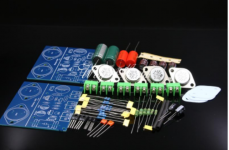
If you want to check the suggested parts types or typical substitutes that will have been discussed here over and over, you have but to read up a few builds in this thread, check the seller's pics of assembled kits on their websites etc. I don't think I have seen these particular boards before but there are quite a few that are similar in having a separate power supply or capacitance multiplier/filter circuit for each amplifier on the same board. I attach a pic below of simpler boards for checking out suitable general parts types.
This item looks close to your boards and is completed, maybe serving as a visual guide :Assembeld Hood 1969 PNP Mj2955 Class a Power Amp Board 2 CH Amplifier | eBay The attached pic only shows parts for the amplifier but you can surely identify the few extra parts used in the regulator sections. Good Transistors to start with would be 6 * MJ15003 (yes, not cheap if genuine), 2 * 2N3906, 2 * BD139-16, taking care to get the pins correct for the smaller transistors as these may be arranged differently. There are an additional 2 * TO92 style transistors near the large smoothing caps, that are probably also identified on the board.
I think there will be problems finding much documentation for PCBs since in China, they don't usually come with lists or schematics that relate to the particular design because all the essential info is printed on it anyway. Considering how few parts there are, how difficult is it to read off the values printed on the PCB and multiply by 2 for a parts list? That's what those guys will be doing if not just buying the kit of parts.
If you want to check the suggested parts types or typical substitutes that will have been discussed here over and over, you have but to read up a few builds in this thread, check the seller's pics of assembled kits on their websites etc. I don't think I have seen these particular boards before but there are quite a few that are similar in having a separate power supply or capacitance multiplier/filter circuit for each amplifier on the same board. I attach a pic below of simpler boards for checking out suitable general parts types.
This item looks close to your boards and is completed, maybe serving as a visual guide :Assembeld Hood 1969 PNP Mj2955 Class a Power Amp Board 2 CH Amplifier | eBay The attached pic only shows parts for the amplifier but you can surely identify the few extra parts used in the regulator sections. Good Transistors to start with would be 6 * MJ15003 (yes, not cheap if genuine), 2 * 2N3906, 2 * BD139-16, taking care to get the pins correct for the smaller transistors as these may be arranged differently. There are an additional 2 * TO92 style transistors near the large smoothing caps, that are probably also identified on the board.
Attachments
Last edited:
this jlh amp kit is a PNP and i do not know if stevec67 is able to tell the difference between a pnp jlh and npn.@ stevec67 ...
I think there will be problems finding much documentation for PCBs since in China, they don't usually come with lists or schematics that relate to the particular design because all the essential info is printed on it anyway. Considering how few parts there are, how difficult is it to read off the values printed on the PCB and multiply by 2 for a parts list? That's what those guys will be doing if not just buying the kit of parts.
If you want to check the suggested parts types or typical substitutes that will have been discussed here over and over, you have but to read up a few builds in this thread, check the seller's pics of assembled kits on their websites etc. I don't think I have seen these particular boards before but there are quite a few that are similar in having a separate power supply or capacitance multiplier/filter circuit for each amplifier on the same board. I attach a pic below of simpler boards for checking out suitable general parts types.
This item looks close to your boards and is completed, maybe serving as a visual guide :Assembeld Hood 1969 PNP Mj2955 Class a Power Amp Board 2 CH Amplifier | eBay The attached pic only shows parts for the amplifier but you can surely identify the few extra parts used in the regulator sections. Good Transistors to start with would be 6 * MJ15003 (yes, not cheap if genuine), 2 * 2N3906, 2 * BD139-16, taking care to get the pins correct for the smaller transistors as these may be arranged differently. There are an additional 2 * TO92 style transistors near the large smoothing caps, that are probably also identified on the board.
I risk having trouble explaining him in English, could you please?
A normal CCS loaded single ended amplifier has a maximum output current in one direction that can never exceed the (CCS set) bias current. (push pull is quite different). But the JLH has a naximum output current that is around 1.5times the bias current in the CCS limited direction.
This extra 50% or so is the result of the modulation on the CCS from the output signal level.
Thanks Andrew. Anyone else like to say more. Did anyone try a MJ3001 as JLH said for the upper device?
nigel, if you come here, would you have in your knowledge an address to buy oem naim pieces (plastic button volume/balance of nait3)Thanks Andrew. Anyone else like to say more. Did anyone try a MJ3001 as JLH said for the upper device?
I just finished one and I only miss it.
I sent an email to Naim and he is no longer...
Thanks Andrew. Anyone else like to say more. Did anyone try a MJ3001 as JLH said for the upper device?
Hi Nigel,
I don't have any MJ3001, but hope to try out a 'descrete' Darlington output stage over the next few days. I'll let you know how it goes.
However, JLH also explianed that the distortion level was a minimum with a high hfe in the lower position. I will try all four combinations, but it will be based on Geoff Mosss' variant.
Regards
Mike
Yes, If stevec67 tried to read part numbers and polarities from my linked Ebay pic, I can see how that would be confusing.this jlh amp kit is a PNP and i do not know if stevec67 is able to tell the difference between a pnp jlh and npn.
I risk having trouble explaining him in English, could you please?
An explanation of PNP v NPN type transistor differences probably isn't necessary but I guess there are several possible reasons why anyone would choose to reverse them from JLH's design. It could be for cost advantage, but I think it would be novelty and an anticipated difference in sound quality that could make such a variation worth selling.
I'll just detail what would need to change if transistor "gender" is reversed. I am not suggesting that stevec do this:
First, TR4 is changed to 2N3904, TR3 to BD140-16 and TR1,2 become MJ15004, MJ2955 or even TIP2955. You can spot such changes quite easily on kits. The opposite gender types chosen here are called complements of those used in the original circuit because they are close to being their electrical mirror twins but fitted just the same, as NPN for PNP or PNP for NPN type.
The regulated DC power supply must also be reversed in polarity by using similar, opposite gender transistors. Then all the polarized components such as the electrolytic capacitors and diodes, zeners, rectifier diodes or bridges must have their +/- terminals reversed too, the caps simply by rotating them 180° in the vertical axis (i.e. normal to the PCB surface). The bridge rectifier connections would require more thought. This is how designs were in the days of germanium transistors, when it was the NPN type that was difficult to make.
I think the PCB could really be the same for either version and still be used as an assembly guide, noting the polarity differences. The only really necessary guide is the PCB itself and the ability to convert the strange markings on the PCB to everyday parts specifications.
Unfortunately, some Chinese boards mix the marking code standards and use whatever suits the space available. There you'll need to apply common sense, read the resistor value with the aid of a colour band chart, look at the schematic and work a few examples through to become proficient. Of course, check any resistor colour bands you first read and calculate, by measurement with a DMM.
Hi Nigel,
I don't have any MJ3001, but hope to try out a 'descrete' Darlington output stage over the next few days. I'll let you know how it goes.
However, JLH also explianed that the distortion level was a minimum with a high hfe in the lower position. I will try all four combinations, but it will be based on Geoff Mosss' variant.
Regards
Mike
instead off mj3001,bdv65(A,B,C) pourrait etre un bon candidat but no to3 package
Thanks everyone on Darlingtons. cumbb, any thoughts? It's the one thing you didn't suggest. My distortion measurements were so good with any old 2N3055 I doubt it is worth trying. I have had no luck with my stereo amp. Far too untidy. I think I should just buy some pcb's.
Yes, If stevec67 tried to read part numbers and polarities from my linked Ebay pic, I can see how that would be confusing.
An explanation of PNP v NPN type transistor differences probably isn't necessary but I guess there are several possible reasons why anyone would choose to reverse them from JLH's design. It could be for cost advantage, but I think it would be novelty and an anticipated difference in sound quality that could make such a variation worth selling.
I'll just detail what would need to change if transistor "gender" is reversed. I am not suggesting that stevec do this:
First, TR4 is changed to 2N3904, TR3 to BD140-16 and TR1,2 become MJ15004, MJ2955 or even TIP2955. You can spot such changes quite easily on kits. The opposite gender types chosen here are called complements of those used in the original circuit because they are close to being their electrical mirror twins but fitted just the same, as NPN for PNP or PNP for NPN type.
The regulated DC power supply must also be reversed in polarity by using similar, opposite gender transistors. Then all the polarized components such as the electrolytic capacitors and diodes, zeners, rectifier diodes or bridges must have their +/- terminals reversed too, the caps simply by rotating them 180° in the vertical axis (i.e. normal to the PCB surface). The bridge rectifier connections would require more thought. This is how designs were in the days of germanium transistors, when it was the NPN type that was difficult to make.
I think the PCB could really be the same for either version and still be used as an assembly guide, noting the polarity differences. The only really necessary guide is the PCB itself and the ability to convert the strange markings on the PCB to everyday parts specifications.
Unfortunately, some Chinese boards mix the marking code standards and use whatever suits the space available. There you'll need to apply common sense, read the resistor value with the aid of a colour band chart, look at the schematic and work a few examples through to become proficient. Of course, check any resistor colour bands you first read and calculate, by measurement with a DMM.
read thisHello to everybody , In search of parts to build a pair of JLH amp and what I have available
Here at my town are MJ2995, MJ 15025 and NPN 15024.
Is MJ 15025 suitable for this project?
Many thanks in advance!
")
mj15024 and 15025 are ok but slow output device are better
I think some pnp have better performance than the npn,it is the only interestPNP or NPN:
To hear differences between commended complementary PNPs and NPNs we must use the self-same parts, because same parts sound different: ergo complete reversing of all parts;-)
And: is the difference ground-minus or ground-plus audible;-? Why, why not;-?!?
and it helps to get rid of the stock of 2n2955
I have both versions in multiple copies at home, I have never heard the difference
- Home
- Amplifiers
- Solid State
- JLH 10 Watt class A amplifier