Just tried what must be the No10 version of a cheap oscillator. It is a single Wien oscillator with damped lamp. The cold resistance of the lamp + 82R is 140R and rises to 146R due to meter current. 300R seems enough to get a reliable gain of 3. The idea here is to ask the same question as people did when the TL071 and LF351N op amps came along. Could one modern op amp beat two LM741's? With a filter stage I think it is just about better with one. Hum seems better. A better use of a NE5532.
The filter is a Chebyshev that is ideal for unchanging frequencies, not great for EQ stages. I found a sweet spot to have near unity gain. The filtering is about 7 dB at 20 kHz which is fine, theoretical would be 10 dB. The Sallen Key filter is the easiest to make and isn't asking the impossible of the op amp, GBP of about 1 MHz needed. Use 33K for circa 1 kHz. You will have plenty to drive a variable resistor.

The filter is a Chebyshev that is ideal for unchanging frequencies, not great for EQ stages. I found a sweet spot to have near unity gain. The filtering is about 7 dB at 20 kHz which is fine, theoretical would be 10 dB. The Sallen Key filter is the easiest to make and isn't asking the impossible of the op amp, GBP of about 1 MHz needed. Use 33K for circa 1 kHz. You will have plenty to drive a variable resistor.
Nige
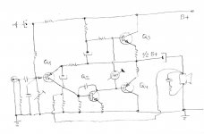
What about this simple JLH1969 `Complementary power pair` four BJT amp alternative ? ,
since in year 1969 Mr.JLH did not have complementary output power pairs available ,
where all four transistors will work in non switching A class regime ,
and where Q1 can be BC212 ,2SA872,..., Q2-2N1711 ,BD139,2SD669 ,..., Q3&Q4- 2N3055/2N2955,-2SC5200/2SA1943,...,
Best Regards
Attachments
CD test disc is a good idea. Thought of it years ago and never followed it up, my brother did me one from his Ferrograph oscillator- test set. I was hoping to get someone to say how they did it. Needs to be near to full output. Not a problem for a test device. Square waves won't be up to much.
NPN- PNP output. Maybe. If the output cap is large enough I doubt I would use extra feedback. It's always been a debate. There might be an issue with the phase inversion the original needs as drawn. It was something I thought about. As feedback is quite high I just looked at it as mostly like a quasi complimentary design when all NPN and no crossover point.
Here's another low distortion idea.
https://www.maximintegrated.com/en/app-notes/index.mvp/id/4547
Last edited:
Nige
Nobody makes this simple A class amp, anyway personally I`m interested in most simple variant with most available BJT`s ,and to be DIY easy&safe for most of DIY members ,
where Q1-BC212 , Q2-2N1711(BD139) , Q3/Q4-2N3055/2N2955 ,with B+ around let`s say 24V / 8 ohm LS , ...
I think that nothing is wrong for output coupling cap if is wrapped in GNFB loop ,
and yes this simple topology is heart of any simple Quasy AB class amp from 60` and 70` .
Last edited:
I believe you are right but for the wrong reasons.
I believe (and there's plenty of discussion several hundred pages ago to support this) that the "niceness" of the JLH '69 comes from the following factors:
1) it's class A. With a decent power supply this means extremely good detail and a "black background" at the low levels we spend 90% of time at.
2) it does not use an LTP diff amp stage. The diff amp is outside the feedback loop and will generate a "flavour". (That is, characteristic distortion products)
3) the asymmetry of the design generates mostly even order harmonics when it does distort on large signals. (Lush, as you put it)
4) When it does clip, it is relatively well behaved. This makes it "louder" than 10W "should" sound.
Most attempts at making the JKH 69 "better" break one or more of the above characteristics, messing with "the sound".
Where the JLH falls over is difficult loads demanding lots of current or voltage swing and/or music with sustained high levels: this is not a result of the architecture but limits of the 2N3055 SOAR curve.
PMA had some good reasons backed by his measurements regarding why JLH is enduringly popular:
"If you do not need high power, this amp is perfect"!
(Underlining add by me)
1st transistor is BC560, driver is BD139 and output devices are MJL21194


One of the big advantages of simple topologies is that they are usually free of hidden local oscillations. In very complex circuits with many local feedbacks, like FB error correction, cascoded VAS, feedforward correction, triple EF, CFP stages etc. it may easily happen that the circuits have VHF local internal oscillations and even the author is not aware of them. It may need very complex instrumentation to find and cure such oscillations.
I have no need to argue with your opinion.
Anyway, I find several important points that might be the reason why this design is timeless.
For home listening, I have measured by oscilloscope and by transient recorder that I do not listen at higher voltage amplitudes than 2Vpeak. And most often it is like 500mV peak. So, the power is not an issue and THD at 100W is totally unimportant at such conditions, but 1st watt (as per Nelson), or rather 1st 100mW are important. The JLH, with its quite high idle current and possibility to give about 1.7x idle current for the reason of phase-inverted drive of the upper and lower output device covers low power area much better than ANY class B or class AB biased somewhere at 200mA. And THIS counts. At low power, the JLH has NO higher harmonics in the spectrum, though with high NFB "low distortion" amplifiers you will find low level high order harmonics (above 9th) as a rule of thumb, if you have enough resolution. This results in a dry, tough sound. These high harmonics are a result of NFB that suppresses low order harmonics at expense of creating high order harmonics, yes in a very low level.
The other important point is that JLH distortion is independent of frequency (which is not the case of the MOSFET PLH).
And, the output impedance is not that non-linear as class AB amplifier's.
So, if you do not need high power, this amplifier is perfect. In case you invite 20 people to listen in a room of 100m2 area, then forget JLH, I agree, and get high power high NFB "up-to-date" design, I agree. In case you need to install a sound system for a rock concert, then go for PA and forget ANY hi-end hifi amplifier.
Originally Posted by Loudthud
I never said that the JLH was a single ended class A amp, but it's distortion profile is not that much different from one.
PMA: Yes, this is correct. But distortion is MUCH lower than that of single ended class A amplifiers with same supply voltage and idle current. Incomparably lower.
Originally Posted by AKSA
After studying this amp in simulation, I notice that as you push it harder, it starts to predominate in H3 and H5.
PMA: No, it does not happen in reality. I have made a huge set of measurements for various supply voltages, idle currents and loads. Near to clipping H3 starts to predominate, but not dramatically. Simulation does not give good results for this amplifier, and extremely depends on accurate models of output devices. Let me show a spectrum near to clipping.
I would like to add that distortion near to clipping strongly depends on idle current and load. The higher the idle current, the lower distortion and contents of higher harmonics. For the reason that the idle current determines characteristic of clipping.
And PMA comments regarding "class A":
JLH is NOT a single ended class A. Both upper output transistor and lower CCS transistor are driven and the CCS is modulated by signal. It is able to give about 1.7 x idle current. Real measurement oft the CCS current attached.


Interestingly enough, the real distortion results I measure are better than those simulated. This is the first circuit with such behavior I have experienced.
Several measurements for a version with power supply voltage +27V, one toroidal center tapped transformer 300VA, two separated bridge rectifiers and filters, one per each channel. Capacitor bank 20400 uF per channel (3 x 6800uF). Common ground for two channels. Idle current 1A per channel.
As one can see, THD depends on voltage (amplitude), but is almost independent on frequency. This is IMO very important. The circuit has OLG about 54 dB with frequency corner above 100kHz. This explains why THD does not depend on frequency in audio range.
After years, it is still very competitive design, in case its limited power is sufficient for the user. As long as JLH plays within its power limits, it sounds very good and will surpass most of contemporary class AB amplifiers.


Originally Posted by AndrewT
I am trying to adjust the tempco of the input transistor and it's CCS to minimise drift in the output offset.
I have been at it for over 4 hours today and a couple of hours yesterday and I'm not in the ballpark yet. I think I am getting closer.
Andrew, I want to keep the original capacitively coupled version. One of the reasons is the possible output DC offset instability, and frankly speaking I do not like the 'improved' circuit designs that appeared after the original version. I bypassed the output capacitor with the 3u3 high quality foil type, and added 2 resistors - 1st to discharge input capacitor to ground (1M) and 2nd to discharge output capacitor when load is disconnected (10k). I also had to add 220pF capacitor + 1k resistor as an input RC, for the reason of faster modern devices used, it was necessary. Output devices are MJL21194 and they do a great job.
... and there is absolutely no initial thump audible, though it is a single rail PSU version with output capacitor. This is probably due to RC time constant (exponential charging) of the filter before the voltage divider used for DC bias of the 1st transistor.
The distortion falls with higher supply voltage. This is for +42V, output swing 16Vpp and 8 ohm load. Just 2nd and 3rd ...
The maximum output voltage swing is about 34Vpp with this power supply. Idle current is 1.5A.

SWEET!
Last edited:
Oh and the 'initial summary':


I built the JLH amplifier in the middle of 1970's and I remember that it was was a real breakthrough, compared to usual class B and AB designs of those days. It sounded very clean, full and natural.
So I have just decided to give it a chance again and to build it with modern solid state devices. I like the original design of 1969 most, for its simplicity and elegance. I have built a sample on a prototype board and supplied it only with +25V supply, which I have unused at the moment. The 1st transistor is BC560, driver is BD139 and output devices are MJL21194. Even with this low supply voltage, the results are stunning. The amplifier is completely free of higher harmonics at any level below clipping, which is the key to its good sound. The OLG is constant high above the audio band. I will probably build a complete stereo amplifier, as I am very curious how it would sound compared to recent amplifiers.
Last edited:
CD test disc is a good idea. Thought of it years ago and never followed it up, my brother did me one from his Ferrograph oscillator- test set. I was hoping to get someone to say how they did it. Needs to be near to full output. Not a problem for a test device. Square waves won't be up to much.
Dead easy with something like Audacity and a CD/RW
Installing and using Audacity. A get you started guide.
Why a "single rail psu" and a output-cap;-?
The complete signal, + and -, works with an INDIFFERENT psu. And with ONE cap: Just ONE, the ONE, the SAME signature/character/noise for the complete signal: LESS NOISE! MUCH CLEANER!
Do not bridge the output cap per little "good ones"-) Except, you do listen per fishy multiways;-)
Bonus: Ergo: NO channel-separate-psus!!! Or right and left channels sound different;-!!!
THANKS !!PMA had some good reasons backed by his measurements regarding why JLH is enduringly popular:
"If you do not need high power, this amp is perfect"!
(Underlining add by me)
1st transistor is BC560, driver is BD139 and output devices are MJL21194
View attachment 658848
View attachment 658849
View attachment 658850
Originally Posted by Loudthud
I never said that the JLH was a single ended class A amp, but it's distortion profile is not that much different from one.
PMA: Yes, this is correct. But distortion is MUCH lower than that of single ended class A amplifiers with same supply voltage and idle current. Incomparably lower.
Originally Posted by AKSA
After studying this amp in simulation, I notice that as you push it harder, it starts to predominate in H3 and H5.
PMA: No, it does not happen in reality. I have made a huge set of measurements for various supply voltages, idle currents and loads. Near to clipping H3 starts to predominate, but not dramatically. Simulation does not give good results for this amplifier, and extremely depends on accurate models of output devices. Let me show a spectrum near to clipping.
I would like to add that distortion near to clipping strongly depends on idle current and load. The higher the idle current, the lower distortion and contents of higher harmonics. For the reason that the idle current determines characteristic of clipping.
I do not know this version ,good candidate for P2P assembly
could we do a real subject on power supply ?
linear,reguled,big capacitor or not ,PI or not PI (that is the question)
For now I will use my LM317 with 2N3055 current booster. I run the 317 from it's own rectifier so as to get a small voltage headroom ( + 2V which it needs ) and lower ripple. There is no feedback from 2N3055 which should keep it very stable, the 317 is just a voltage reference with bags of current if needed, far less trouble than a TL431. To my surprise the Indian 3055's have a gain of 100 at 1amp doing this which is good to see. The big advantage here is a standard 25V rms transformer can be used with very little extra heat output from the need to regulate. It is linear as it is the most logical choice other than lead acid batteries ( accumulators ). 20 000 uF main cap and 10 000 uF for the LM317. I have these parts so why not ? The 10 000 uF is dented, it's fine at low current. It's one I have used many times to try out ideas. If not 2200 uF would be fine.
One thing people never say is in an amplifier like this we have 3 ouput stage devices. Bottom 2N3055 voltage amplifier converted to current amplifer using negative feedback. Upper current sink ( ??? ) and then a semi ridged current amplifier which is also a 3055 when me ( PSU ). The class AB Quad 303 doing the same except the 3055 ( current source ) is to the -ve rail causing speaker minus not to be at ground. It must be that the first 2N3055 in the power supply is a device changing the sound. It is doing more work than the next two devices at the critical low levels where detal is heard.
To be honest I can't see a Pi filter being good enough. There again I am assuming the power supply rejection ratio to be poor. JLH seems always to use a regulated supply. BTW, my idea should not colour the sound too much as it is simple. It's the very circuit I was told to avoid in 1974 at college. Not exactly, that was the current amplified zener. I have added a LM317 to be the zener. I did try the zener idea with Darlington and CCS, it was less good.
Taking the point that T03 cases are likely not to be as good as T0247 sound wise I will clamp a tag to the case upper side with flying wire. I will also add ferrules with long wires to the emitter and base. These will be hard wired points. The way I have the first try-out design is too fragile.
My heat sink is about 0.25C/W. It will run 36V at 2.4 amps total. With luck 50C max at the heatsink in the summer ( 27C perhaps, no aircon, we Brits seldom need it ). It has 8 x T03 holes and 5 x 2N3055 ( E ). The spare holes are ideal to run wires through.
I have 4700 uF 100V output caps. Usually the 100 V types have better tan theta as the foils are larger to avoid flash over. I will add 10 uF high grade. Gain, RC filtering and bootstrap will be 330uF Panasonic FC types. The circuit diagram I used had the bootstrap at 2000uF. I shall try 330 uF as I think that was more typical. As so many time constants are circa 4Hz I might use either 470 nF or 4.7 uF input.
I am trying to get a list together of people to tell when I move house. I might do 4 hours on this today if I can.
BTW. I have a hunch my oscillator I showed yesterday is better than my test gear. And it is cheap. For 1 kHz you can use the same output filter I think or add 10 and 100 nF ( 900 Hz ) to op amp 2. A 4 pole 3 way rotary switch is enough to house the parts. Output should always be above 1 Vrms which should suit most things. 1.6 Vrms being typical.
Usually I like cap multipliers. If the 1969 JLH I prefer a fixed voltage type.
I have the planned JLH 70% built now. For the first time in my life I have stopped early to do the 30 % when I next have time, if I pushed to do 100% doubtless there would be a problem. If it works OK I am tempted to epoxy pot the point to point wiring.
I have the planned JLH 70% built now. For the first time in my life I have stopped early to do the 30 % when I next have time, if I pushed to do 100% doubtless there would be a problem. If it works OK I am tempted to epoxy pot the point to point wiring.
Here you go Nigel, another free offering with quite a range of tones and some interesting optional test features that you can play directly as FLAC, APE or WAVPACK files or burn a CD if you prefer something in solid, 16 bit/44.1 format. It's also a UK product so I expect you would be able to get help if needed.
Test CD
Test CD
thank's !Here you go Nigel, another free offering with quite a range of tones and some interesting optional test features that you can play directly as FLAC, APE or WAVPACK files or burn a CD if you prefer something in solid, 16 bit/44.1 format. It's also a UK product so I expect you would be able to get help if needed.
Test CD
i use this
keuwlsoft - Download.com
could we do a real subject on power supply ?
linear,reguled,big capacitor or not ,PI or not PI (that is the question)
For far too long I've been planning on replacing the current series regulated supply with a choke input filter. Primarily to see if the noise level goes down: the additional self regulation won't be visible on a Class A amp.
Have found:
2N3055, Motorola?, older ones, aluminium-body, hfe 10 - 70
Kuhlkorper Alukuhlkorper mit 2x 2N3055 Leistungstransistor TO3 | eBay
2N3055, Motorola?, older ones, aluminium-body, hfe 10 - 70
Kuhlkorper Alukuhlkorper mit 2x 2N3055 Leistungstransistor TO3 | eBay
Evening gents,
I've received the PCBs, following advice on here and elsewhere I went for a blank PCB so that I can buy my own genuine parts here in the UK or from reputable sellers like OnSemi.
The only snag is that I don't have a parts list or schematic, so I don't yet know what I am building or what's in it. The PCB is 2-sided, I bought his one.
2pcs JLH 1969 class A amplifier amp stereo high quality bare PCB 10W DIY audio | eBay
It looks to be good quality, I am told that it's the original cicuit, based on TO3 package 2N 3055s with a 3rd one each side that seems to be set up as a voltage regulator. Has anyone used these boards and do they have a schematic? If you have a parts list, better again.
for the list part, all references are printed on the pcb
for the diagram, you will find it on another kit with reguled psu on the net.
they are all the same.
for the setting, it's like the others, a pot for setting the middle point of the psu voltage and the other for the quiescent current
for the diagram, you will find it on another kit with reguled psu on the net.
they are all the same.
for the setting, it's like the others, a pot for setting the middle point of the psu voltage and the other for the quiescent current
- Home
- Amplifiers
- Solid State
- JLH 10 Watt class A amplifier