I'm not sure why some are saying the slower parts are better. Could anyone shed any light on this?
Simulations show that the high frequency response with the original slow 2N3055's is pretty poor. But to check this you will need a slow 2N3055 model. Most SPICE models match the faster epi devices.
Modern fast devices give clearly improved frequency response, but need (in practice and simulation) a small compensation capacitor wrapped around the feedback resistor.
Epi devices in the region of 2-4MHz will give a better response than the slow 3055's but not as fast as the new devices. The high emitter-base capacitance may limit the response as a driver transistor is not used in front of the OP devices, but simulations should have accounted for this. Maybe that is something to check regarding the "fast" transistor models.
the simulations are good but in the case of the JLH, I'm not sure it's a good thing.
I have often seen amp that were not good in the simulations but much better than the others in reality.
in my case, I tried a lot a lot of output transistors and in any case, the slowest of the less fast were always the best.
on the other hand, for the small signals, the fastest ones are the best if they are silent.
I also think that one should look in a scientific manner on this schema to finally know the verity.
as I said, I have several at home and all 69, they almost all the same small signal bjt, but all different output device, and they all have a different sound
I have recently become aware that during manufacture that high hFE and Early Voltage are inversely proportional.Ian
Why are C grade i/p devices to be avoided? Asking cos Ive got buckets of BC550/560C!
If you have the same device in different grades from the same process, then high Early Voltage usually means low hFE and conversely, high hFE means lower Early Voltage.
This may be why in this amplifier that higher Early Voltage is more desirable than higher hFE.
I don't know, so the above is just a guess.
I often think that we are like ants at the feet of the designer.
that we gesticulate in all directions and that with a little experience we happen to understand something.
I often imagine real designers reading and laughing at us by looking at problems that are simple for them
that we gesticulate in all directions and that with a little experience we happen to understand something.
I often imagine real designers reading and laughing at us by looking at problems that are simple for them
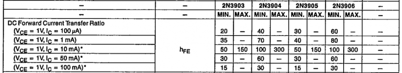
If you look at the spec. of the original 2N3906 part that JLH selected, you realize it's not a high gain part by today's standards. Excessive gain throughout results in instability with the JLH and if any of you bother to read JLH's articles plus later comments by Geoff Moss and others in the transistor substitutes section, you can read why. You'll find the best collection with support articles and recommended substitutes at The Class A Amplifier Site (TCAAS). It's now hosted as an archive at Rod Elliott's ESP website. Scroll down to the articles index here: http://sound.whsites.net/index2.html
Times and parts specs have changed since 1969 and we need to keep an eye on where we are going if sustituting ever higher performance parts. This is not a long tail pair input stage where high gain, bandwidth and matching are essential for optimum performance.
The attached table is what JLH would have seen as the gain (Hfe) spec. Compare this with BC550C, for example. http://www.onsemi.com/pub/Collateral/BC550C-D.PDF
Depending on where you bought those BC550Cs, you may find that they're not actually to spec. anyway. I have seen Ebay store BC550C, 2SC945, 2SC1815 etc that were all the same basic product, apparently marked or re-marked to demand, even with the wrong pinout. Very cheap and according to a curve tracer, they were similar to BC548 but I didn't have the opportunity to test much further.
Attachments
JLH with Darlington output stages and other stuff
HI Folks,
I said I would report back on how I got on experimenting with the JLH Class A power amp and using Darlingtons in the output stage.
To set the scene, my day to day amp is a Geoff Moss version of the JLH with a high current capability (the ESL version). I use this one because my monitors (B&W Matrix 80 Mk3) can dip down to about 4 ohms in their impedance curve, which means that a normal JLH will have problems driving it at high levels as it not the most efficient of speakers. This amp has 2 sets of output transistors (MK15003) with 0.1 ohm current balancing resistors. You can find the details of this on the Class A amp website
Having experimented with that quite a bit, I replaced the driver/phase splitter with a Szikla pair having a gain of about 3. The measured distortion dropped by about the same value and to my ears the mid range cleaned up: things like the trailing edges of piano notes seem to just be there. You can 'hear the room' on some recordings which all adds up to me of the amp really controlling the speakers. The bass also was something to die for – gut wrenching. The only stability task was a 47pF from the collector to base of the NPN on the Szikla Pair.
By upping the power rails to +/- 30 volts and increasing the standing current, it gives a comfortable 40 watt and get nice and warm. Distortion is down at about 0.0035% or so. Although I have to admit, I cannot hear the difference below 0.1 % and I think that most people would be the same in a double blind test.
I built 2 mono blocks with separate power supplies in another box. You can see some pictures in post 3497 of this thread.
Ever the experimenter, I decided to try and up the output power a bit – aiming for about 60 to 80 watts and see if the distortion could drop down a bit more, (‘cos I can) so this is why I had a play with the Darlington output stage, but I made a discrete version as I don’t have TO-3 Darlingtons around. I used the MJ15003 with a BD139-16 in front of it and a 100 ohm resistor across the MJ15003 base to emitter.
The pcb I made can be used for the standard Moss configuration or the S-Pair mod so I tried 4 combinations all with a single output pair and I used the same output transistors for all the tests.
The upper MJ15003 has a hfe of 66 and the lower a hfe of 73 and the power rails are+/- 22volts from a stabilised bench supply (my trusty Skytronics). The heatsinks are really big and get up to about 24 degrees above ambient.
The variants I tried are as follows:
(a) The standard Moss version - baseline configuration for reference
(b) The Moss version with a S-pair driver
(c) Version (a) with a Darlington output
(d) Version (b) with a Darlington output
I measured the distortion for a couple of output voltages: 2.8, which equates to about 1 watt into 8 ohms, and 6.3 volts, which is about 5 watts.
Note that these are all measured values into an 8 ohm dummy load – no simulations in sight.
The results look very promising (for some reason I can't get the formatting right on these figures)
(a) Standard Moss config
O/P volts, Iq, Distortion(%)
2.8, 1.9A, 0.004
6.3, 1.9A, 0.01
(b) Moss version with a S-Pair having a gain of 3X
Vout, Iq, Distortion (%)
2.8, 1.9A, 0.0013
6.3, 1.9A , 0.003
These figures seem about right since we are increasing the open loop gain by a factor of 3 and I would expect the distortion to drop by about the same.
Now the good stuff.
To add the Darlington stage I obviously had to make some adjustment to the current setting circuit as it now has to provide less current to the output stage due to their enormous hfe values, which means that it is under less stress.
Interestingly, I did not have to retune the notch filter in the Radford DMS-4, which implies that there was no discernible phase shift by adding the BD139.
The Darlingtons had a hfe of 7070 for the upper and 9460 for the lower.
(c) Standard Moss config with Darlington output
Vout, Iq, Distortion (%)
2.8, 1.9A, 0.0016
6.3, 1.9A, 0.0036
(d) Moss Config with S-pair and Darlington output
Vout Iq Distortion (%)
2.8 (1 Watt), 2.0A, 0.0007
6.3 (5 Watt), 2.0A, 0.001
This seems good so I carried on a bit.
10V (12.5Watt), 0.0018
11V (15 Watt), 0.0022
12V (18 Watt), 0.0024
13V (16.9 Watt), 0.003
14V (24.5 Watt), 0.008 – onset of clipping
The low power distortion figures for (d) are approaching the limits my equipment which is Viktors low distortion oscillator and a Radford DMS-4. The lower limit is about 0.0003% distortion reading. Viktor's oscillator is at least a decade down on this.
So what about listening: I tried the (d) config and could not hear any difference against my day to day amp I mentioned above. The main thing however, is that it opens the door to some high power outputs since it puts less load onto the driver stage.
The figures seem to imply that the S-Pair, acting as a voltage amp of 3x, drives the output more linearly and the Darlington supplies more grunt to the output stage reducing distortion even more.
So folks over to you, it works albeit a bit fidly. How you do the above on the JLH69 I leave to you – experiment some more yourselves
Best regards.
Mike
HI Folks,
I said I would report back on how I got on experimenting with the JLH Class A power amp and using Darlingtons in the output stage.
To set the scene, my day to day amp is a Geoff Moss version of the JLH with a high current capability (the ESL version). I use this one because my monitors (B&W Matrix 80 Mk3) can dip down to about 4 ohms in their impedance curve, which means that a normal JLH will have problems driving it at high levels as it not the most efficient of speakers. This amp has 2 sets of output transistors (MK15003) with 0.1 ohm current balancing resistors. You can find the details of this on the Class A amp website
Having experimented with that quite a bit, I replaced the driver/phase splitter with a Szikla pair having a gain of about 3. The measured distortion dropped by about the same value and to my ears the mid range cleaned up: things like the trailing edges of piano notes seem to just be there. You can 'hear the room' on some recordings which all adds up to me of the amp really controlling the speakers. The bass also was something to die for – gut wrenching. The only stability task was a 47pF from the collector to base of the NPN on the Szikla Pair.
By upping the power rails to +/- 30 volts and increasing the standing current, it gives a comfortable 40 watt and get nice and warm. Distortion is down at about 0.0035% or so. Although I have to admit, I cannot hear the difference below 0.1 % and I think that most people would be the same in a double blind test.
I built 2 mono blocks with separate power supplies in another box. You can see some pictures in post 3497 of this thread.
Ever the experimenter, I decided to try and up the output power a bit – aiming for about 60 to 80 watts and see if the distortion could drop down a bit more, (‘cos I can
) so this is why I had a play with the Darlington output stage, but I made a discrete version as I don’t have TO-3 Darlingtons around. I used the MJ15003 with a BD139-16 in front of it and a 100 ohm resistor across the MJ15003 base to emitter.The pcb I made can be used for the standard Moss configuration or the S-Pair mod so I tried 4 combinations all with a single output pair and I used the same output transistors for all the tests.
The upper MJ15003 has a hfe of 66 and the lower a hfe of 73 and the power rails are+/- 22volts from a stabilised bench supply (my trusty Skytronics). The heatsinks are really big and get up to about 24 degrees above ambient.
The variants I tried are as follows:
(a) The standard Moss version - baseline configuration for reference
(b) The Moss version with a S-pair driver
(c) Version (a) with a Darlington output
(d) Version (b) with a Darlington output
I measured the distortion for a couple of output voltages: 2.8, which equates to about 1 watt into 8 ohms, and 6.3 volts, which is about 5 watts.
Note that these are all measured values into an 8 ohm dummy load – no simulations in sight.
The results look very promising (for some reason I can't get the formatting right on these figures
)(a) Standard Moss config
O/P volts, Iq, Distortion(%)
2.8, 1.9A, 0.004
6.3, 1.9A, 0.01
(b) Moss version with a S-Pair having a gain of 3X
Vout, Iq, Distortion (%)
2.8, 1.9A, 0.0013
6.3, 1.9A , 0.003
These figures seem about right since we are increasing the open loop gain by a factor of 3 and I would expect the distortion to drop by about the same.
Now the good stuff.
To add the Darlington stage I obviously had to make some adjustment to the current setting circuit as it now has to provide less current to the output stage due to their enormous hfe values, which means that it is under less stress.
Interestingly, I did not have to retune the notch filter in the Radford DMS-4, which implies that there was no discernible phase shift by adding the BD139.
The Darlingtons had a hfe of 7070 for the upper and 9460 for the lower.
(c) Standard Moss config with Darlington output
Vout, Iq, Distortion (%)
2.8, 1.9A, 0.0016
6.3, 1.9A, 0.0036
(d) Moss Config with S-pair and Darlington output
Vout Iq Distortion (%)
2.8 (1 Watt), 2.0A, 0.0007
6.3 (5 Watt), 2.0A, 0.001
This seems good so I carried on a bit.
10V (12.5Watt), 0.0018
11V (15 Watt), 0.0022
12V (18 Watt), 0.0024
13V (16.9 Watt), 0.003
14V (24.5 Watt), 0.008 – onset of clipping
The low power distortion figures for (d) are approaching the limits my equipment which is Viktors low distortion oscillator and a Radford DMS-4. The lower limit is about 0.0003% distortion reading. Viktor's oscillator is at least a decade down on this.
So what about listening: I tried the (d) config and could not hear any difference against my day to day amp I mentioned above. The main thing however, is that it opens the door to some high power outputs since it puts less load onto the driver stage.
The figures seem to imply that the S-Pair, acting as a voltage amp of 3x, drives the output more linearly and the Darlington supplies more grunt to the output stage reducing distortion even more.
So folks over to you, it works albeit a bit fidly. How you do the above on the JLH69 I leave to you – experiment some more yourselves
Best regards.
Mike
There are some points to consider regarding the input stage transistor. As this operates with a minimal collector voltage variation, Early effect distortion will not be as significant as in the driver transistor stage. That would suggest a high gain device would not be a problem. However, what I do see as a limitation is that the emitter resistor in the feedback network- I like to call the feedback resistor Rf and the associated resistor which is grounded at one end (even through a capacitor) Rg - is 220 ohms. That is going to be the major limitation as it will set the input stage transconductance to about 1/300 mA/V whatever gain grade of transistor is used (including its own gm).
Lower distortion can be achieved by simply reducing the Rg to increase the OLG and making an appropriate change in Rf, but perhaps not by more than 2x reduction.
Regarding the output stage, I too have considered using driver transistors to improve the overall linearity. I have an experimental design simulated but not tested. I wondered if a separate thread on this might be something worth considering : a JLH-D perhaps.
good idea..............
Regarding the output stage, I too have considered using driver transistors to improve the overall linearity. I have an experimental design simulated but not tested. I wondered if a separate thread on this might be something worth considering : a JLH-D perhaps.
I look forward to seeing both Threads.
JLH-D and JLH-S
And post4368 can be copied across.
Last edited:
New Thread?
Hi Andrew and John,
I think your suggestion of a new thread is a good one as it would allow this line of experiment to go off on its own tangent and leave the 'pure' (i.e. 1969) version to continue without confusion or complication.
My thought would be that a single thread would be better as there is bound to be some interaction between the two aspects - Szikla VAS/driver and the standard or Darlington output stage.
As I said in my post, my experiments are based on the Geoff Moss variant which is fundamentally a different way to control the quiescent current and the offset voltage.
I would be happy to start this new thread and copy my post over along with the spreadsheet I did for the power calculations etc. I suppose it would probably be useful for other people if I put the circuit diagrams into Viso or the like.
Incidentally, John Ellis's point about changing the feedback resistors had also occured to me but for different reason. My amp is driven from a mixer that outputs 0VU = 1.28 volts so I wanted less sensitivity and dropped Rf down to 1k5 and Rg down to 120R in series with a 50R preset to get exacly 26dB gain.
Thoughts, comments.
Kind regards
Mike
Attach your pic and info. It remains here for as long as DiyAudio exists. And use the attach method that keeps the pic on the same page.............. I suppose it would probably be useful for other people if I put the circuit diagrams into Viso or the like.
I've already posted
Seems no-one wants to take it up to consider, yet.
don't worry, leave them time to jump on their simulator and after the critics will fall
not diy - but would there be opinions which of these 3 JLH amps would be the "best" overall?
10W*2 Super Deluxe A amplifier Hifi 2.0 channel amplifier Electronic filtering hood 1969 Class A amplifier 10W*2-in Amplifier from Consumer Electronics on Aliexpress.com | Alibaba Group
2017 New SA1969 hifi Pure Class A HOOD 1969 Audio Power Amplifier HiFi Stereo 10W Microphone AMP finished board-in Amplifier from Consumer Electronics on Aliexpress.com | Alibaba Group
2017 Breeze Audio Voice king Hood 1969 glod sealed the most perfect version of the HD1969 class A power amplifier 10W+10W-in Amplifier from Consumer Electronics on Aliexpress.com | Alibaba Group
These use virtually the same amplifier boards with electronically filtered power supplies so what you are left to compare is just the case, transformer type and possibly its slightly different supply voltage and hum issues.would there be opinions which of these 3 JLH amps would be the "best" overall?
I have the 3rd example and find it performs well enough but thermally it's a problem after an hour or so as it heats up and with that, also the volume control - That's not good but I have a fix in mind for it.
All 3 have heatsinks that are really too small for the the way they are mounted directly to the chassis so the whole amplifier becomes quite warm all over after a hour or so. If you want to choose, pick from the 2 with toroidal transformers - these are less likely to emit an annoying buzz at the constant 2.5A supply current used. They are not regular factory products with rigid design control over components and testing etc. so this is really taking a guess about the particular product you might receive. I think it will come down your idea of good appearance and price
...less likely to emit an annoying buzz at the constant 2.5A supply current used.
This is one reason I'm keen to try a choke input supply: any capacitor input supply is going to be under some stress at 5A (stereo).
My standalone regulated power supply has a custom damping element (a spare bible) "mounted" on top to stop the chassis rattling.
thanks Ian - maybe a PC fan base blowing air up and over the anemic heatsinks would help. I have a Monarchy Audio amp and somewhat familiar with AlephJ ~ 35yr ago had a Belles A which was modified to class AB (much "brighter" and more "forwards" presentation on Magnepans ) and sorta remember a Bedini 10/10 w. 2N3055 - does the JLH sound like any of those amps?
(I've some 2 1/2 pound EI air gap 8mHy/0.3ohm crossover chokes which might carry 5A -?)
(I've some 2 1/2 pound EI air gap 8mHy/0.3ohm crossover chokes which might carry 5A -?)
Well, the load current is actually only 2.5A DC total for both channels, which is not so bad. In my experience with this little feller and a few other fun builds of my own, any small buzz hasn't yet warranted a choke. I hazard a guess that power transformers become noisy when they are dealing with high currents with short, low resistance windings. This 2x10W rated amplifier seems to have about a 120VA transformer and 2 x 22VAC windings, one for each amplifier in a dual mono arrangement and it makes no mechanical noise at all through its metal shield, though it may not be true for all the products you are considering.
I also have a 2 x 20W class A amplifier that uses about a 160VA custom toroid with 2 x 17V windings and similar DC output current of 2.6A in series. That buzzes noticeably, so the kit designers (Silicon Chip magazine here) recommended a pair of ferrite ring chokes be fitted in what I understand is a resonance damping arrangement.
You are on the right track with a fan but slow it with only around 1/2 voltage supply to make it silent and maybe use two. Just raising my amp off the shelf on an old heatsink reduced the case temperature by about 8°C and I think anyone could be creative with ventilation if they wanted to - it's just that as a retail product, I expected someone to have thought this through or maybe I just don't know what to expect with such dirt cheap prices.
About comparisons there, I have to be honest and say I've never directly compared any of those US models with a JLH'69. I heard a pair of Monarchy 70s playing loud at a promotion for retailers and AV installers in my area some years back and I thought they were excellent but in a very different class to a JLH'69.
The JLH design is really about easy, low cost DIY for the average dude nearly 50 years ago when affordable solid state amplifiers were still a bit crude and oozing crossover distortion. Silicon transistors were still expensive and the fewer the better in the UK. There's only 4 transistors in there but the class A sound quality was still a breath of fresh air by comparison to typical commercial solid state designs of the day. Somewhat like Nelson Pass's Zen models, there's some spice in the residual harmonic distortion mix of such simple designs and that is what really keeps them popular
A very simple idea came up that T03 is not as good sounding as other case types. I went to my shed and sure enough all were made of steel. If only silver plated copper. If anyone has copper T03's let us know with a magnet test. To be honest not to make T03's from copper is bonkers as it has ideal electrical and thermal conduction. Silver is slightly less reactive and looks nice, 60 micron plating is thought to be best it can be. It would also take solder to the case top if required. Before anyone says it, many amps using T03's sound great.
Unlike most designs I doubt if NPN or PNP is a big deal. I can not make my JLH as time has run out with the house move. I will keep reading and can start in April. Best PCB's for 1969 version?
Unlike most designs I doubt if NPN or PNP is a big deal. I can not make my JLH as time has run out with the house move. I will keep reading and can start in April. Best PCB's for 1969 version?
- Home
- Amplifiers
- Solid State
- JLH 10 Watt class A amplifier