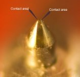
It varies, but generally somewhere in the conical section and usually one can see the witness line. For the S-120 it's probably not shown on that image, because of the scale.LD: where does the diamond end and the shaft start on that?
It's easier to see in the image below from the archive, which is also marked up to point to the location of the only bits that matter: the contact regions.
The resolution needed to see detail in the contact regions is impossible with optical microscopy, unfortunately. And the same problem with detail on corresponding groove walls.
One can see how different styli are made, and especially the true-biradials such as the nude 2M Blue I posted previously which differe from pseudo elipticals in obvious ways.
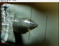
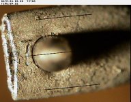
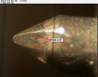
Anyways, here's another bonded one with a markup of contact points. Tiny aren't they ? Also see how the base point shape varies, as per my critique of the Hunt/Barlow/Walton indentation method. This one ends in a fine chisel like shape.
LD
Attachments
Last edited:
These are made with a biology/pathology lab optical microscope, BTW.
These with industrial RV equipment
(optics) Olympus rigid borescope
(camera+electronics) Karl Storz Technopack
Shure M97 xE cartridge
N97xE stylus with biradial (elliptical) diamond tip, 5 x 18um
(.0002 x ,0007 in.)
George
Attachments
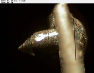
Some nice shots. Unfortunately a change of settings at purge central means it's not caching the images as there are some very nice ones showing how the wear patch growns into a teardrop and due to the marvel of pixel counting how large it is. A few of these look good enough for that as well.
Some nice shots.
These picture always remind one of the distribution of results in micro fabrication. I wonder if some kind of nano-3D printing could ever be used here?
A little test of the rust proofing.Love the new Avatar Scott")
Also verify the electrical harness in the lower engine compartment is indeed IP68
PS I had to drive through such deep water twice, one with a BMW R67 motorbike and later with a Skoda Felicia auto. Neither of them failed to drive out of the waters (air intake above the water, exhaust below the water, keep steady rpm).
George
PS I had to drive through such deep water twice, one with a BMW R67 motorbike and later with a Skoda Felicia auto. Neither of them failed to drive out of the waters (air intake above the water, exhaust below the water, keep steady rpm).
George
I must stop falling down rabbit holes. I discovered an interesting theory on the way some manufacturers create the HF lift in MCs that I must test one day, but back onto track, and hoping LD is listening...
There was a long thread which I fear is now lost trying to tie up compliance measurements and in particular converting japanese 100Hz measurements to european 10Hz meaurements. Was wondering what your current thinking was on this?
There was a long thread which I fear is now lost trying to tie up compliance measurements and in particular converting japanese 100Hz measurements to european 10Hz meaurements. Was wondering what your current thinking was on this?
Bill, I can’t help with the compliance thread you're seeking. However, I question any “rule” purporting to relate 100Hz “compliance” to that at 10Hz. First of all, what is meant by “compliance”? A stylus suspension has mechanical impedance – a complex value having a real (springiness) and an imaginary (damping) part. Both real and imaginary parts can vary with frequency and temperature.
At issue is the mechanical admittance (reciprocal of impedance). At 10Hz it’s the real part of admittance (compliance) that’s of practical interest since it governs tonearm resonance frequency. But at 100Hz, it’s the total admittance that’s of interest since that limits maximum modulation amplitude that can be tracked.
My understanding is that 10Hz compliance values are typically determined by measuring stylus resonance frequency when loaded with a known mass (i.e., tonearm effective mass) at specified VTF. I’m not sure how 100Hz values are determined experimentally. (Perhaps by modulation tracking limits? Or by exciting the stylus mechanically?)
Refer to my post #1222 and the curves showing mechanical properties of butyl rubber, typical for a stylus suspension bung. Both the real (springiness) and imaginary (damping) values can be derived from these curves. One could compare 10Hz and 100Hz values and formulate a “rule” to relate them. But this rule would only be valid at one temperature.
If the stylus design includes a metal tie wire, additional suspension stiffness in introduced, essentially invariant with frequency and temperature.
Sometimes a “static compliance” is specified. Is this determined by direct measurement of stylus deflection under VTF load? i.e., “0Hz compliance”? Not very meaningful for judging either tonearm resonance frequency or modulation trackability.
Hi Charlie,
I'm a lot more happy with the concept of 10Hz and 100Hz compliance being completely different measurements of completely different mechanical properties than there being some relationship. It doesn't help that manufacturers quote different things with no DIN std much of the time. Pain. I will re-read your earlier post and scan the thread in case this was actually all covered and I forgot.
I'm a lot more happy with the concept of 10Hz and 100Hz compliance being completely different measurements of completely different mechanical properties than there being some relationship. It doesn't help that manufacturers quote different things with no DIN std much of the time. Pain. I will re-read your earlier post and scan the thread in case this was actually all covered and I forgot.
After many delays finalising the load resistors for my balanced aurak build and slightly frustrated by lack of suitable measuring setup at home as the published figures do not always fill me with confidence. Anyway taking the best I had to hand found something interesting, which is that most of the cartridges I had to hand need about the same load.
Cart R(Ohms) L(mH) 2L-R
Ortoton OM 750 450 150
SuperOM 1000 580 160
S120 1680 920 160
AT150 530 350 170
AT440MLa 610 490 320
Other than the 440 they are all within +/-7% . Tempted to just match some 80Ohm resistors and correct any residual in DSP. As the errors will be low down where I am crossing over to a sub anyway all bets are off for flat response without correction
I know I'm talking to myself here but whilst messing around calculating the effect of using a single input resistance for all the cartridges (+/-7Hz on the turnover frequency) something started nagging me. Although the 2L-R works as a nice easy rule, upping the series resistance to IIR 800Ohms moves the turnover to 500Hz and saving a zero in the design.
I'm clearly missing something obvious, but not sure what...
but whilst messing around calculating the effect of using a single input resistance for all the cartridges (+/-7Hz on the turnover frequency) something started nagging me. Although the 2L-R works as a nice easy rule, upping the series resistance to IIR 800Ohms moves the turnover to 500Hz and saving a zero in the design. I'm clearly missing something obvious, but not sure what...
whilst messing around calculating the effect of …moves the turnover to 500Hz
Hi Bill
Are you doing simulations?
George
Hi Bill, Charlie explained it properly above, IMO.I must stop falling down rabbit holes. I discovered an interesting theory on the way some manufacturers create the HF lift in MCs that I must test one day, but back onto track, and hoping LD is listening...
There was a long thread which I fear is now lost trying to tie up compliance measurements and in particular converting japanese 100Hz measurements to european 10Hz meaurements. Was wondering what your current thinking was on this?
There can't be a deterministic way of converting between compliance specifications for 10Hz and 100Hz cases because they mean different things for entirely different purposes.
100Hz compliance is a restatement of what VTF is needed to achieve a certain trackability. That's how it is measured, Charlie: what VTF is required to track a 50um amplitude 100Hz groove, IIRC. From which, mechanical impedance is deduced, and expressed as though it were obtained by a spring at 100Hz. Whereas in practice impedance at 100Hz is more obtained from damping than spring.
I once wrote a calculator that used spec VTF and compliance (at either 10Hz or 100Hz) to 'triangulate' and estimate true values for both spring and damping so long as at least one of the compliance figures was known. It wasn't bad, IIRC. I have it somewhere in the archive........
But common rules of thumb for converting are just wild guesses really, and pretty useless. The focus on resonant frequency, rather than its Q, is where the train left the rails some decades ago, IMO..........
LD
Refer to my post #1222 and the curves showing mechanical properties of butyl rubber, typical for a stylus suspension bung. Both the real (springiness) and imaginary (damping) values can be derived from these curves. One could compare 10Hz and 100Hz values and formulate a “rule” to relate them. But this rule would only be valid at one temperature.
Not that it matters I'm used to the loss (damping) usually as heat as being real and the oscillatory (frequency) part as imaginary. But in any case the equations are second order with mass, compliance, and damping having L, C, and R equivalents as analogs.
- Home
- Source & Line
- Analogue Source
- mechanical resonance in MMs