I browse old electronics magazine and take printout of interesting articles (only analogue related) and read at leisure. There is an article in Audio Engineering magazine June 1953 about lateral mechanical impedance in pickups. Would that be helpful ? Also there was another article by Mr. Villchur (or Mr. Walton ?) of three ways of calculating compliance but I forgot where it was. Will post soon.
Last edited:
Yes, it's all a construct to help maths of analysis of course, but conventionally spring and inertia each have imaginary impedance (ie multiplied by sqrt(-1) ) with opposite signs, and damping has real impedance which is always positive.Not that it matters I'm used to the loss (damping) usually as heat as being real and the oscillatory (frequency) part as imaginary. But in any case the equations are second order with mass, compliance, and damping having L, C, and R equivalents as analogs.
When literature or charts refer to 'impedance', typically they refer to magnitude of impedance - which doesn't adequately describe it. It's such sloppy maths that allows impedance at 100Hz to be expressed as compliance as though it came from a pure spring. Tut tut tut. And, IMO, apparently it led to decades of confusion that still persists today........ and more or less complete silence as to damping, one of the most important parameters affecting cart-arm performance.
LD
Last edited:
Hi Bill,I know I'm talking to myself herebut whilst messing around calculating the effect of using a single input resistance for all the cartridges (+/-7Hz on the turnover frequency) something started nagging me. Although the 2L-R works as a nice easy rule, upping the series resistance to IIR 800Ohms moves the turnover to 500Hz and saving a zero in the design.
I'm clearly missing something obvious, but not sure what...
Not sure whether I understand your remark correctly, maybe the image below may give you some answers.
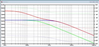
FR for the 3 signals were taken with a flat (non Riaa) input signal, with the amplitudes normalised.
1) The green line represents the FR of the Cart plus the (2L-R) resistor, giving a -3dB at 316 Hz.
2) The Blue curve shows the correction to curve 1) caused by R11/C1, shifting the -3dB point to 2.12Khz (75usec).
3) And R27/C5 are responsible for the 318usec and 3180usec Riaa time constants, shown here in red.
Hans
Attachments
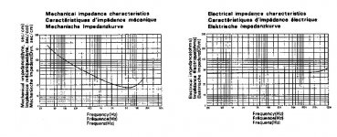
Thank you all. My question was piqued by the following chart. Bad scan but this is the Denon DL-304*, which interests me as it's an 'air coil' design with no lump of pig iron that the coils are wound around which should/could/might have an effect on effective mass.
My first thought was 'that's useful, why didn't more manufacturer plot that' then I wondered what was missing, then I just got annoyed that everyone gives spot points and for different parameters with no test method.
*Yes I know MC issues need a seperate thread, but the what to measure and how is kinda on topic
Attachments
Not that it matters I'm used to the loss (damping) usually as heat as being real and the oscillatory (frequency) part as imaginary. But in any case the equations are second order with mass, compliance, and damping having L, C, and R equivalents as analogs.
Thank you Scott. Indeed, I had the real and imaginary parts reversed. At one time I would have known better. But now . . .
Why 500Hz? The Riaa time constant at 500Hz is a zero and not a pole as the (2L-R) gives at 316 Hz.Hans, yes that was my understanding, Just wondering why 316Hz not 500Hz other than the easy maths. I know there is something large and obvious staring me in the fact on this
There is no easy math involved.
The 316 Hz is just a value caused by the (2L-R) that could be altered in (1,85L-R) or (2,25L-R) or whatever, as long as your cart fits the bill.
But in your case the (2L-R) happens to result in almost the same resistor for all of your carts, being an excellent choice for that reason.
Hans
Right, whilst waiting for the mouser order* I've been thinking about damping as LD keeps reminding us that this is what matters and, having finally got my head around what Ortofon did with the S-120 (brilliant and completely obvious when the penny drops) trying to work out how it could be done for other cartridges.
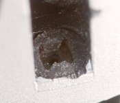
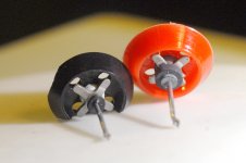
Quick recap. The S-120 has a second donut (shown in photo) which has a batman logo cut into it. So if the stylus is moving in the horizontal plane or at up to +/-45 degrees, it does nothing. Once you get over 45 degrees it starts to damp and decrease compliance. It took a while for it to sink in that mistracking was the stylus 'catching air' and when it did this extra doohickey suddenly made a lot of sense. The challenge now is how to make something that acts the same way for other cartridges that could be fitted by the likes of us?
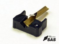
Second picture is of a jico stylus which is the same basic pattern used on almost everything that is not AT or ortofon, from My old A&R P77 to George's M97. I can't help thinking that it should be possible to cut a couple of rubber diamond shapes which, with one tip nipped off would give you the same effect. Maybe even a glorp of silicon sealant shaped in there?
*Mouser order is here. Time to solder
Quick recap. The S-120 has a second donut (shown in photo) which has a batman logo cut into it. So if the stylus is moving in the horizontal plane or at up to +/-45 degrees, it does nothing. Once you get over 45 degrees it starts to damp and decrease compliance. It took a while for it to sink in that mistracking was the stylus 'catching air' and when it did this extra doohickey suddenly made a lot of sense. The challenge now is how to make something that acts the same way for other cartridges that could be fitted by the likes of us?
Second picture is of a jico stylus which is the same basic pattern used on almost everything that is not AT or ortofon, from My old A&R P77 to George's M97. I can't help thinking that it should be possible to cut a couple of rubber diamond shapes which, with one tip nipped off would give you the same effect. Maybe even a glorp of silicon sealant shaped in there?
*Mouser order is here. Time to solder
Attachments
I stand no chance of reading this whole thread. But I can tell you I put GR-research no-rez dampening material on key locations of my stylus (it's three sides are flat) and a little on tonearm. It's not real practical to buy a sheet for just this purpose... but anyone in the USA I can send a tiny bit to, to try. The difference stopped me from buying a new stylus for better performance.
Another big problem I found with MM's, is that they can wiggle back and forth a little, as many mount not nearly firmly enough as they push into the cartridge. If you have any wiggle you must find a way to stop it.
The irony I find is that I love how MM's can replace the stylus, where as MC's that often don't require to send it in for re-tipping.
Pardon for Just a little bit of overthinking about rubber bearing holding stylus.
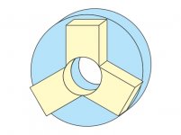
only vertical rubber bearing (like Batman) will probably hurt stereo image and minute details. And I guess stylus will catch air only on loud passages in any direction. So we need a dual compliance rubber bearing. How about two thin slice of different compliance rubber as shown in picture. Seen from front the offwhite high compliance will hold stylus in place and will be free to move in any direction. being high compliance the thee point will present less resistance. The light blue rubber bearing at backside will be low compliance and with slightely bigger hole. so when greater excursion of stylus takes place on loud passeged it resists and damps the movement resulting in keeping more or less constant touch with groove walls.
only vertical rubber bearing (like Batman) will probably hurt stereo image and minute details. And I guess stylus will catch air only on loud passages in any direction. So we need a dual compliance rubber bearing. How about two thin slice of different compliance rubber as shown in picture. Seen from front the offwhite high compliance will hold stylus in place and will be free to move in any direction. being high compliance the thee point will present less resistance. The light blue rubber bearing at backside will be low compliance and with slightely bigger hole. so when greater excursion of stylus takes place on loud passeged it resists and damps the movement resulting in keeping more or less constant touch with groove walls.
Attachments
If you look at the photo carefully you will see the regular donut behind. This is a second damper to JUST handle the excursions due to mistraking. So dual compliance is exactly what Ortofon have done. Many cartridges have different compliance vertical to horizontal, but this appears different in that +/-45 degree movement where the stylus is in the groove are not affected, only out of phase signals, which are generally eq'd out at least at the low end. As long as the vinyl is pushing the diamond there is no problem but when lift off is attempted then this is resisted.
Bill, Possibly what Ortofon is attempting is to use an omnidirectional low-damping high-compliance donut elastomer (so not to hinder modulation trackability) at the rear as general support, then add a different high-damping low-compliance elastomer (at low frequencies) "bat" piece effective only in the vertical direction for tonearm resonance suppression. Since there is limited vertical low-frequency modulation, trackability is not as issue. Just a guess.
Well the specified horizontal compliance is 11cu*, so it's higher than say the nightclub DJ range but waaay lower than the hifi range at 25cu. remember mistracking is not necessarily tonearm resonance driven, it's just the stylus getting airborne for any reason.
*no frequency or test methodology given, phooey.
*no frequency or test methodology given, phooey.
OK. Didn't knew such method was already incorporated. At minute level things are so interrelated and complex. Reading multiple threads I guess a good compromise is mid/high compliance low mass stylus with properly damped arm. Need to study tonearm inertia and weight distribution and how it affects the working of a tonearm. Any article on that subject online ? Bias effect is a subject in itself.
Regards.
Regards.
Low mass is good. If you read things LD has posted lower compliance could possibly be better as low compliance tends to mean better damped.
We haven't even started on the minutae of tonearms yet! And if we are not careful this will be another case of LD pointing out that everything we though we knew was wrong
We haven't even started on the minutae of tonearms yet! And if we are not careful this will be another case of LD pointing out that everything we though we knew was wrong
Over the weekend have discovered what might be the best cartridge for experimenting with. This is the venerable B&O SP series of MI. Whilst the moving mass might be a tad high, you can get at all the moving bits to mess around with damping concepts. May not be the greatest performer, but will allow theories to be tested by those of us hammy of fist
Attachments
Bill,
Damping at stylus will be miniscule so with out test record will be difficult to discern. Right ? I am reading some old magazines. There was an Audio Technica' Cartridge advertisement. Its stylus after elastomer bearing had screw to adjust compliance. Also Reading (Printed copy of downloaded articles) 'Limiting factors in gramophone records' by Mr. Barlow. It is in two parts. The second part (Wireless World June 1957) includes comprehensive factors affecting stylus. Like vertical / lateral resonance, damping at stylus etc. Probably you already know about this but if not; download and do read. As mentioned few times earlier my brain stops functioning when charts and formulas suddenly appear on paper . But see if you can find some relevant information and post it here in simple language.
Thanks and regards.
Damping at stylus will be miniscule so with out test record will be difficult to discern. Right ? I am reading some old magazines. There was an Audio Technica' Cartridge advertisement. Its stylus after elastomer bearing had screw to adjust compliance. Also Reading (Printed copy of downloaded articles) 'Limiting factors in gramophone records' by Mr. Barlow. It is in two parts. The second part (Wireless World June 1957) includes comprehensive factors affecting stylus. Like vertical / lateral resonance, damping at stylus etc. Probably you already know about this but if not; download and do read. As mentioned few times earlier my brain stops functioning when charts and formulas suddenly appear on paper
. But see if you can find some relevant information and post it here in simple language. Thanks and regards.
Most of the damping of the stylus vibration should be there at the stylus and it is significant. But there are many vibration modes and each needs examining to see what can be done.
If you look at the S-120 it's a bonded spherical, but tracks 30% larger LF modulations that almost anything else in the ortofon catalogue. All from a rubber donut with a batman logo cut into it
If you look at the S-120 it's a bonded spherical, but tracks 30% larger LF modulations that almost anything else in the ortofon catalogue. All from a rubber donut with a batman logo cut into it
- Home
- Source & Line
- Analogue Source
- mechanical resonance in MMs