On semi doesn't tool up their production line to make ****y parts on purpose. The 2n3055/MJ2955 they are selling now are likely identical to MJ15015/16, but with a different marking. They might leave a heat spreader out of the case. If going to run at extended rail voltage, I would take some "2n3055" and do a Vceo test with a 100 v or 80 v source, a 10 k resistor and a current meter. If they don't leak more than 10 ma at 80 v or 100 v they are likely much more voltage resistant than RCA homotaxial (1965-1975) parts.
Warning use one hand at a time messing with >24 v, and no jewelry at all. 30 vdc across your heart can stop it.
The parts I'm using don't have beta of 5 either @ 2 amps, however hard it was to get 2 amp beta in 1975. Beta droop is a 1975 phenomon, not endemic to exptaxial parts now whatever the simulator model says. Do some tests with 10 ohm collector resistor & 100 ohm base resistor to test this theory. I got Vce of .11 to .14 v @ gain 10 on some higher rated parts, which shows incredible saturation.
The batch of 2n5401 I bought last year had beta of about 300 even though that violates the spec for maximum gain. I'm running at 70 v rail and 400 kohm base pull down resistor for my amp input transistor.
BD139-140 for the amp in post 665 with 63 v rails, I don't think so. Check those at that voltage for Iceo, same test as above. No leaky at 70v, okay. If you can get them, MJE15028/29 15030/31 or 15030/32 are specified for that voltage and down from $4 apiece 2 years ago to $1.30 now. If you can't get those, TIP41C/42C worked for me for both drivers and VAS. With those slow parts, Ft 3 mhz the very highest of tinkly bells weren't quite right, but everything else was. Takes very well cared for ears (mine top out at 14 khz) to hear the problem.
I've used TIP41C/42C from fairchild at 70 v collector voltage, no problem. Driver service. I do use a heat sink.
Last edited:
fo MJ15015/6 is so expensive here
simulate first then real life
that's what i will take before burning money
Wise precaution. Simulation costs nothing, and it could help avoid too many mishaps with the real thing.
fake 3055s, in INDONESIA there are many cheap fake of them especially from manufacturer in CHINA
you know, most seller here thinking money than quality
Wow! I didn't know fakes were circulating. At least I haven't heard of any in europe or usa.
well, i don't know if RCA making first original 3055/2955
They did. They were the first and originator of the 3055, but the 2955 didn't exist then. Only the NPNs were around, so that's why so many quasi amps were around and using all NPNs.
i tell to you and other else, my amplifier 300watt stereo
i am forget to tell you one channel is 150watt so 2 channel stereo is 300watt
Well, not 300W for one amp, then, it's 2 x 150W, 150W per amp, but still a big lie. Even at 4ohms, 150W just isn't possible.
So it's a lie, and I'm not going to be politically correct about it
On semi doesn't tool up their production line to make ****y parts on purpose. The 2n3055/MJ2955 they are selling now are likely identical to MJ15015/16, but with a different marking.
You're probably right. So our modern 3055s may handle 120V and not 60V.
Beta droop is a 1975 phenomon, not endemic to exptaxial parts now whatever the simulator model says. Do some tests with 10 ohm collector resistor & 100 ohm base resistor to test this theory.
That's an interesting proposition. I'll have to do some sims on that.
BD139-140 for the amp in post 665 with 63 v rails, I don't think so.
That's what I said
I think it would be a risky proposition to use those at that rail level.
TIP41C/42C worked for me for both drivers and VAS.
Those don't have a tremendous beta, and they're rated for 100V.
I've used TIP41C/42C from fairchild at 70 v collector voltage, no problem. Driver service. I do use a heat sink.
Well, that would indicate they really handle more than their rated 100V, but it's always a bit of a gamble.
you mean like this one???
http://www.diyaudio.com/forums/atta...mplifier-based-2n3055-ocl-400-watt-sanken.gif
i've just open google and found it...
Again - Purely Mythical Output Power...
@ spookydd: This ist EQUA's schematics:
Best regards!
Last edited:
On semi doesn't tool up their production line to make ****y parts on purpose. The 2n3055/MJ2955 they are selling now are likely identical to MJ15015/16, but with a different marking. They might leave a heat spreader out of the case. If going to run at extended rail voltage, I would take some "2n3055" and do a Vceo test with a 100 v or 80 v source, a 10 k resistor and a current meter. If they don't leak more than 10 ma at 80 v or 100 v they are likely much more voltage resistant than RCA homotaxial (1965-1975) parts.
Warning use one hand at a time messing with >24 v, and no jewelry at all. 30 vdc across your heart can stop it.
The parts I'm using don't have beta of 5 either @ 2 amps, however hard it was to get 2 amp beta in 1975. Beta droop is a 1975 phenomon, not endemic to exptaxial parts now whatever the simulator model says. Do some tests with 10 ohm collector resistor & 100 ohm base resistor to test this theory. I got Vce of .11 to .14 v @ gain 10 on some higher rated parts, which shows incredible saturation.
The batch of 2n5401 I bought last year had beta of about 300 even though that violates the spec for maximum gain. I'm running at 70 v rail and 400 kohm base pull down resistor for my amp input transistor.
BD139-140 for the amp in post 665 with 63 v rails, I don't think so. Check those at that voltage for Iceo, same test as above. No leaky at 70v, okay. If you can get them, MJE15028/29 15030/31 or 15030/32 are specified for that voltage and down from $4 apiece 2 years ago to $1.30 now. If you can't get those, TIP41C/42C worked for me for both drivers and VAS. With those slow parts, Ft 3 mhz the very highest of tinkly bells weren't quite right, but everything else was. Takes very well cared for ears (mine top out at 14 khz) to hear the problem.
I've used TIP41C/42C from fairchild at 70 v collector voltage, no problem. Driver service. I do use a heat sink.
well, from what you said
looks like i have chance for increasing voltage but i will not take it
for other transistor i can't say anything cause i have no them all right now
but thanks for your suggestion, now i have more idea for this one
Wow! I didn't know fakes were circulating. At least I haven't heard of any in europe or usa.
luckily you live in great country and have strong regulation
Well, not 300W for one amp, then, it's 2 x 150W, 150W per amp, but still a big lie. Even at 4ohms, 150W just isn't possible.
So it's a lie, and I'm not going to be politically correct about it
why???
because they are stereo???
and it make power supply should produce more power???
tell me your calculation
if i am not wrong...
here this is my calculation...
2N3055 MJ2955 can handle more than 90v so
i have 35VDC dual power suply and 10amps...
so it means 2x24Vx10A=480watt
but the worst of AB class is only have 65% efficiency
at the last this amplifier can only producing 312 watt stereo or 156watt per channel
if the amplifier have load 4 ohm
for 8 ohm 156watt/2 = 78watt
tell me if i am wrong
Last edited:
Again - Purely Mythical Output Power...
@ spookydd: This ist EQUA's schematics:
Best regards!
i know this one fake...
because single power source, not dual power source cannot gives more power and stability...
that's why i hate non dual power supply
Again - Purely Mythical Output Power...
@ spookydd: This ist EQUA's schematics:
Best regards!
Thanks!
Capacitor coupled, and no ltp front end.
Old design.
That reminds me that my very first power amp, that was 3055 based, quasi, in the 60s, was also capacitor coupled. Very similar.
why???
because they are stereo???
Stereo makes no difference. A stereo amp is just a pair of mono amps.
If the power supply is shared, they're still two amps, although they can bother each other by pulling on the same PSU.
It's not a matter of mono or stereo, just a matter of voltage and impedance.
and it make power supply should produce more power???
tell me your calculation
Well, just like I and others have said earlier, it's a quick calculation:
150W (rms) on 4ohms, demands about 24.5V rms (sqrt(P*R)), which is almost 35V peak already. Plus the Vcesat from the devices and some loss in the emitter resistors, that's several more volts. In that amp, the emitter resistors are 0.47ohms, and when the power peaks at fairly close to 35V (if it could), the load draws not very far from 9Amps, and that much current in the 0.47ohms resistor is a little over 4V.
So the overhead has some 4V plus the Vcesat. Assuming those trannies saturate fairly strongly (onset of clipping), but they're also carrying a serious current, even shared among 2 devices, that's still maybe a couple more volts of Vcesat.
So we're already at some 6V, possibly a little more, just in overhead, and that's when the rails are sagging the most, so the load needs close to 35V peak on it, for 150W rms, plus about 6V, that's some 41V peak, while the rails are sagging. This means where there is no load on that PSU, the rails could be several volts above that, perhaps an other 5 or 6, or more.
So if you need to output 150W rms into 4ohms (resistive. sine), then your rails at rest should be at least some 47-48V or a bit more.
Obviously you're nowhere near that with your unloaded rails at 35V.
So here you go, no way to pull 150W from that amp on 4ohms.
2N3055 MJ2955 can handle more than 90v so
If you're lucky. On the new devices, and you can verify they can. Because it's not certain, just probable.
i have 35VDC dual power suply and 10amps...
so it means 2x24Vx10A=480watt
but the worst of AB class is only have 65% efficiency
at the last this amplifier can only producing 312 watt stereo or 156watt per channel
if the amplifier have load 4 ohm
for 8 ohm 156watt/2 = 78watt
Well, that's not how you should calculate the power output of an amp.
This would be totally misleading.
tell me if i am wrong
You are!
You don't calculate the output power by calculating its power consumption and efficiency.
So if you need to output 150W rms into 4ohms (resistive. sine), then your rails at rest should be at least some 47-48V or a bit more.
Obviously you're nowhere near that with your unloaded rails at 35V.
So here you go, no way to pull 150W from that amp on 4ohms.
so...
is it possible for putting 45VDC or 30VAC in my rails with 10Amps on this circuit???
or i will make white smoke only???

because i've heard about "more amps it means more watt but with correct voltage", is that true???
cause this statement are so trendy in my country
example, my friend assembling APEX-B1000, then he gives them VDC parallel power supply one from 15Amps trafo and second is 10Amps trafo
#update : with 24VAC at 75% volume for 3 hours playing bass and sub tone, the transistors are only warm, also its heat sink not feel hot too much
i give big and tight heat sink
Last edited:
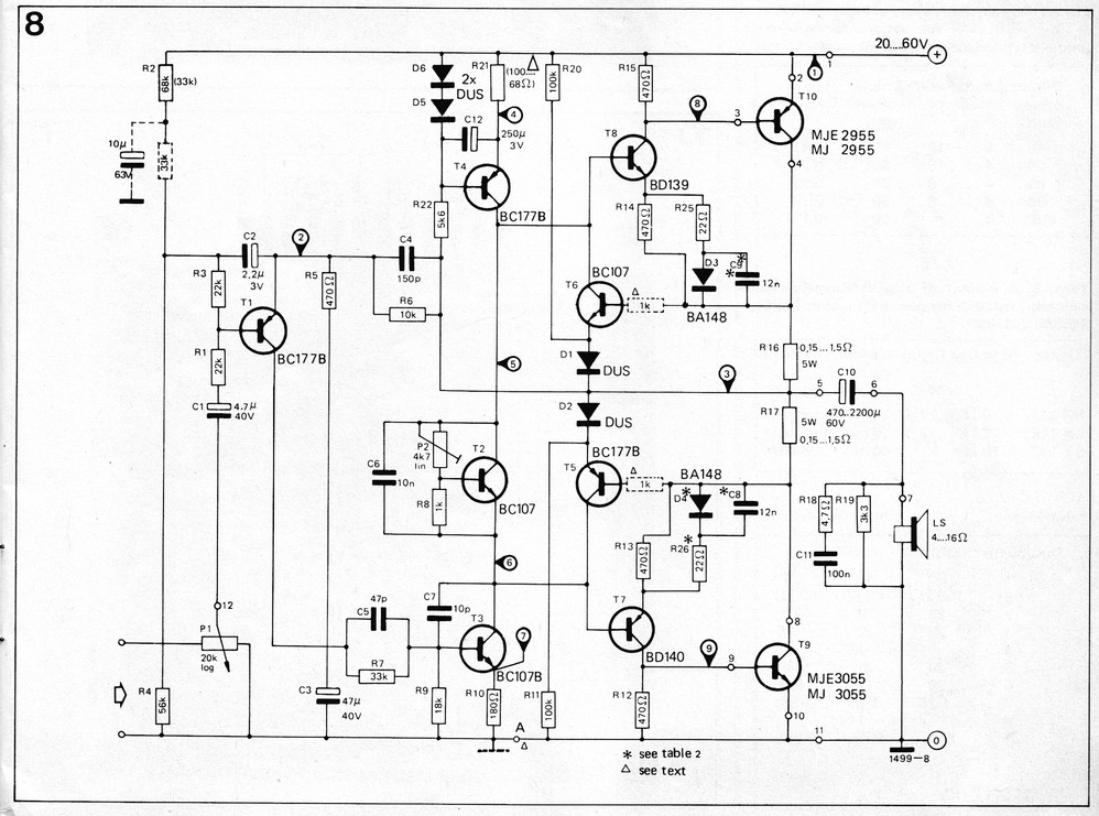
I was curious about that amp with the japanese parts, so I made a quick sim of it.
It's the same topology as the 3055 version, except mostly for the extra pre-driver stage (3EF), so although it's not a 3055 amp, I'm posting it here because this is where we're discussing it.
I suspect similar results to be expected from the 3055 (2EF) version.
For one thing, with the bias resistor left at 220ohms as on the schematic, there is hardly any bias flowing in the output, nearly nill on the negative side, a few mills on the plus side.
So I biased it at about 100mA per output device, rather rich, because I noticed heavy distortion.
The gain is around 41 (a little over 32db), and as it's not a symmetric design, as I expected, it starts clipping on one side before the other, so it clips on the negative side first, which brings the onset of clipping level down some.
At that onset of clipping level, it takes 1.36V (peak) to drive it. The load being 4ohms pure resistive.
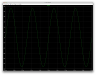
The sine wave look somewhat ok, but that's at 1khz, and it gets bad when going up in frequency.
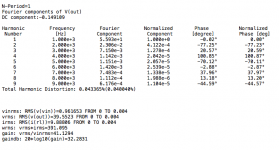
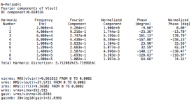
At 1khz the THD doesn't look overly bad. We're at full power, before clipping, about 391W rms on a 4ohms load.
But things change when raising frequency, a lot. I got more than 5% distortion at 20khz, and the input level would require adjustment to retain the same power level, because of the gain drop, from the overly narrow bandwidth.
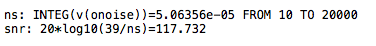
Noise isn't a concern, as it's close to 118db SNR (referred to 39Vrms output).
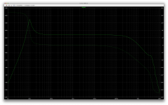
The AC analysis reveals a big gain spike at 10hz. From the plot shape, I suspect some issues may be there when open loop.
It's the same topology as the 3055 version, except mostly for the extra pre-driver stage (3EF), so although it's not a 3055 amp, I'm posting it here because this is where we're discussing it.
I suspect similar results to be expected from the 3055 (2EF) version.
For one thing, with the bias resistor left at 220ohms as on the schematic, there is hardly any bias flowing in the output, nearly nill on the negative side, a few mills on the plus side.
So I biased it at about 100mA per output device, rather rich, because I noticed heavy distortion.
The gain is around 41 (a little over 32db), and as it's not a symmetric design, as I expected, it starts clipping on one side before the other, so it clips on the negative side first, which brings the onset of clipping level down some.
At that onset of clipping level, it takes 1.36V (peak) to drive it. The load being 4ohms pure resistive.
The sine wave look somewhat ok, but that's at 1khz, and it gets bad when going up in frequency.
At 1khz the THD doesn't look overly bad. We're at full power, before clipping, about 391W rms on a 4ohms load.
But things change when raising frequency, a lot. I got more than 5% distortion at 20khz, and the input level would require adjustment to retain the same power level, because of the gain drop, from the overly narrow bandwidth.
Noise isn't a concern, as it's close to 118db SNR (referred to 39Vrms output).
The AC analysis reveals a big gain spike at 10hz. From the plot shape, I suspect some issues may be there when open loop.
Attachments
-
 Screen Shot 2017-01-31 at 10.13.40 PM.png556.9 KB · Views: 230
 -
 Screen Shot 2017-01-31 at 10.13.52 PM.png210.2 KB · Views: 247
 -
 Screen Shot 2017-01-31 at 10.14.17 PM.png56 KB · Views: 170
 -
 Screen Shot 2017-01-31 at 10.53.11 PM.png55.9 KB · Views: 157
 -
 Screen Shot 2017-01-31 at 10.56.03 PM.png9.8 KB · Views: 142
 -
 Screen Shot 2017-01-31 at 10.57.45 PM.png339.1 KB · Views: 105
is it possible for putting 45VDC or 30VAC in my rails with 10Amps on this circuit???
If you're lucky and all the devices handle the extra voltage, it may work, although perhaps not at full power. Running out of SOA maybe...
It all depends on how much voltage the parts can sustain. We do know they many will handle more than the stated 60V for the 3055s, and 80V for the BD139/40, but when you raise up your rails, you're taking the risk, unless you properly test the devices first, to make sure they can handle it.
or i will make white smoke only???
It's a distinct possibility, but you could get lucky, maybe.
because i've heard about "more amps it means more watt but with correct voltage", is that true???
It wouldn't matter if your PSU could do 100Amps, or 200Amps, it doesn't matter, they're not the ones "pushing" their amps to the load, it's the load "pulling" those amps from the PSU, via the devices, according to how much voltage they apply to the load.
As my previous quick calculations showed, in the hypothetical case that you had enough rail voltage to put out 150W in 4ohms. That was some 46-48V rails or more, if they don't sag too much. Then the peak amps would be a little less than 9Amps, so a 10Amps capable PSU would do it. As long as it also provides at least the 46-48V rails, or better. Or you just won't get those 150W. Just less.
cause this statement are so trendy in my country
There was a time when I heard many statements of power that were "max", "music", "program", "peak", whatever... It's all rubbish! Th real watts are RMS.
I was curious about that amp with the japanese parts, so I made a quick sim of it.
It's the same topology as the 3055 version, except mostly for the extra pre-driver stage (3EF), so although it's not a 3055 amp, I'm posting it here because this is where we're discussing it.
I suspect similar results to be expected from the 3055 (2EF) version.
For one thing, with the bias resistor left at 220ohms as on the schematic, there is hardly any bias flowing in the output, nearly nill on the negative side, a few mills on the plus side.
So I biased it at about 100mA per output device, rather rich, because I noticed heavy distortion.
The gain is around 41 (a little over 32db), and as it's not a symmetric design, as I expected, it starts clipping on one side before the other, so it clips on the negative side first, which brings the onset of clipping level down some.
At that onset of clipping level, it takes 1.36V (peak) to drive it. The load being 4ohms pure resistive.
The sine wave look somewhat ok, but that's at 1khz, and it gets bad when going up in frequency.
At 1khz the THD doesn't look overly bad. We're at full power, before clipping, about 391W rms on a 4ohms load.
But things change when raising frequency, a lot. I got more than 5% distortion at 20khz, and the input level would require adjustment to retain the same power level, because of the gain drop, from the overly narrow bandwidth.
Noise isn't a concern, as it's close to 118db SNR (referred to 39Vrms output).
The AC analysis reveals a big gain spike at 10hz. From the plot shape, I suspect some issues may be there when open loop.
you are right, at 80% volume negative side getting warmer first and bass sub looks like never reach its peak
the same issue you got it looks like first time using this amplifier before
treble tone never reach its peak after 70% volume...
feels like hanging
on the 90% volume, output sounds looks like getting little lower
i think it happens because its needed more amps
but the reality it's not
that's what happened
#update : with 24VAC at 75% volume for 3 hours playing bass and sub tone, the transistors are only warm, also its heat sink not feel hot too much
i give big and tight heat sink
Well, for one thing, using it for a sub only, reduces the bandwidth that it reproduces quite a bit. Although the bulk of the energy is in the low end, not having most of the audio bandwidth to reproduce brings down some of the strain.
Plus whatever that 75% volume may be, it's probably not the power at which the amp dissipates the most.
The issue of the breakdown voltage on the devices only is a bigger concern when they have to make the full swing, close to the rails, when they "see" the most Vce, and if the volume isn't so high, only some fast transients can push that voltage swing way up. This may not happen too much if the filter cuts out the high speed transients.
Plus that amp has an input filter that seem to cut the bandwidth some.
A big heatsink is always better than a small one. It may keep them nice and cool, but even if they're cool, when the volume is higher and the devices are exposed to the full swing, then they could breakdown if they can't handle that voltage, even if they're barely warm.
You're probably ok with those new devices, as they're more likely to handle more than the stated 60V.
on the 90% volume, output sounds looks like getting little lower
i think it happens because its needed more amps
but the reality it's not
The rails may be sagging too much.
If they do, you may have much higher distortion, from clipping.
It all depends on how much voltage the parts can sustain. We do know they many will handle more than the stated 60V for the 3055s, and 80V for the BD139/40, but when you raise up your rails, you're taking the risk, unless you properly test the devices first, to make sure they can handle it.
i think i will not take the risk before changing the voltage reaching its limit so i will change the voltage using 28VAC only, i will recoil again my trafo
It's a distinct possibility, but you could get lucky, maybe.
gambling with no guarantee for best result
It wouldn't matter if your PSU could do 100Amps, or 200Amps, it doesn't matter, they're not the ones "pushing" their amps to the load, it's the load "pulling" those amps from the PSU, via the devices, according to how much voltage they apply to the load.
my PSU can handling it cause i give 20Amps diode rectifier
There was a time when I heard many statements of power that were "max", "music", "program", "peak", whatever... It's all rubbish! Th real watts are RMS.
this is it!!!
you and mooly have been saying it before
you and other people in this forum have been changing my mindset!
for the next project(my own or reservation by someone) i will make amplifier circuit playing in the safe area
not needed too much modification or something that strange like "give more power" but amplifier circuit can not handling it
Well, for one thing, using it for a sub only, reduces the bandwidth that it reproduces quite a bit. Although the bulk of the energy is in the low end, not having most of the audio bandwidth to reproduce brings down some of the strain.
Plus whatever that 75% volume may be, it's probably not the power at which the amp dissipates the most.
The issue of the breakdown voltage on the devices only is a bigger concern when they have to make the full swing, close to the rails, when they "see" the most Vce, and if the volume isn't so high, only some fast transients can push that voltage swing way up. This may not happen too much if the filter cuts out the high speed transients.
Plus that amp has an input filter that seem to cut the bandwidth some.
A big heatsink is always better than a small one. It may keep them nice and cool, but even if they're cool, when the volume is higher and the devices are exposed to the full swing, then they could breakdown if they can't handle that voltage, even if they're barely warm.
You're probably ok with those new devices, as they're more likely to handle more than the stated 60V.
you are right > The issue of the breakdown voltage on the devices only is a bigger concern when they have to make the full swing, close to the rails, when they "see" the most Vce, and if the volume isn't so high, only some fast transients can push that voltage swing way up. This may not happen too much if the filter cuts out the high speed transients.
if this amplifier circuit playing song with full range frequency(20-20KHz) the voltage swing away like my first measuring, never stable in 35VDC
i think it comes from electrolytic caps then i change them with 3couples of 4700uF/50V but it only help 2 or 3 volts only
for 60v area or higher watt i will change the final transistor first...
gambling i snot an option...
gambling with no guarantee for best result
You got that right!
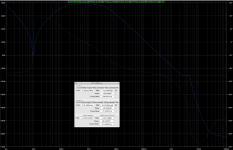
I just ran the tian probe to see what the open loop gain looks like and get a reading on the phase and gain margins.
Amazingly, there isn't a huge amount of phase shifting in the useful band, so at unity gain, we're still at about -100 degrees of shift, giving about 80 degrees of phase margin. At least there's that. Then the phase shifting kicks in higher gear but not enough to bother it, and we end up with decent gain margin of about 15.6db. That part isn't bad and the amp seems stable.
But the oddity is at 10hz. It's funny how the closed loop gives such a huge gain spike right there at 10hz, from the 32 and some db nominal gain, to close to 45db at the height of the gain spike. And the open loop instead has just about zero gain at that same 10hz, and a big phase reversal happens right there.
I wonder what causes this, maybe the bootstrapping?
Since this amp is so similar to yours, even with the extra pre-driver stage, it probably behaves similarly.
Perhaps mooly could use his sim that he made earlier and let us know how that one behaves.
Attachments
Amazingly, there isn't a huge amount of phase shifting in the useful band, so at unity gain, we're still at about -100 degrees of shift, giving about 80 degrees of phase margin. At least there's that. Then the phase shifting kicks in higher gear but not enough to bother it, and we end up with decent gain margin of about 15.6db. That part isn't bad and the amp seems stable.
But the oddity is at 10hz. It's funny how the closed loop gives such a huge gain spike right there at 10hz, from the 32 and some db nominal gain, to close to 45db at the height of the gain spike. And the open loop instead has just about zero gain at that same 10hz, and a big phase reversal happens right there.
I wonder what causes this, maybe the bootstrapping?
Since this amp is so similar to yours, even with the extra pre-driver stage, it probably behaves similarly.
not only you get it using sims, last few days i have been testing this one using my friend oscilloscope
the phase shifting stay at -90 till -110 degree then kicking like trying for completing its power
unfortunately, i am forget for recording it
bootstrapping problem???
i think yes cause bootstrapping part so simple, but i have some ideas from my friends
i will testing it using sims first then i will tell you
but this is what i like from this circuit
this circuit don't costing too much electrical bill but can producing good sound(for home entertainment also small family and my neighbours ceremony, like praying(i am a muslim so there are some ceremony using religion song), karaoke or independence day)
Last edited:
for 60v area or higher watt i will change the final transistor first...
gambling i snot an option...
Perhaps there is one other thing that could be done. If they are available where you are and cheap enough, there are the 2N3442 and BDX20.
Those are possible drop-in 3055 replacements.
They're very similar in most respect: same power dissipation, same case, a little less gain for the 3442, and only 10A instead of 15, but that lower current handling isn't an issue in this case, and most of all, the lower current trades for much higher Vce0, as they're 140V rated.
The one thing that's kind of bad with those is they're slower, much slower.
But I've used power amps before based on those 3442 devices, and they worked just fine, full range.
Although they handle less peak current than the 3055, they're still pretty rugged in comparison, and with 140V guaranteed breakdown voltage, there is no way you'll break them that way. So big heatsink and here you go, with higher rails.
The key is to find them, and if they're cheap enough.
They are still available on mouser for example, but only the 2N3442 and not its BDX20 complement. It all depends on what's available where you are.
I have old stock of all those devices, 3055s, 2955s, 3442, bdx20, bdx18, 2n3773, etc... All from the 60s and 70s, so no fakes for sure.
That 2N3773 could also be possible, if you could also find its complement the 2N6609, but that may be unlikely, and if they're cheap enough anyway.
- Home
- Amplifiers
- Solid State
- Amplifier based on 2N3055