you can be an "informed customer", or a gullible customer.
That's your choice.
I know that that advertising is untruthful !
You have had time to become "informed", but you still cling on to a completely untruthful claim.
You DON'T know how to design amplifiers despite what you post
yep...
i will make my declaration...
cause i wish too much and expecting more about this amplifier
until i make other new amplifier, i will using it
of course your words is good ones
and i will take it
it means, i will saving my money for my next better amplifier
your words got support from my cousins here...
he said, don't refuse what you said cause you are right
after he showing his result using oscilloscope about this amplifier(ha has the same one also same brand too)
thank you very much
i can't posting his picture(his result) cause at his home(far away from big city) the internet connection is too slow for mobile phones
Well, you simply believed false advertising that's all. You wouldn't be the first one to fall for it.
But now I suspect you're getting more informed and can figure out when you're being lied to.
yeah...
you are right...

Wow! What a difference when going from 22u to 47u for that input cap!!!
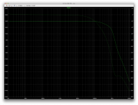
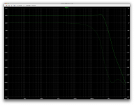
It doesn't change anything about the frequency response, which is not bad at all for a 3055 amp, but the thd drops like a stone and now the highest level of thd is where it's common, at the high end.
Still not bad even at 20khz.
It doesn't change anything about the frequency response, which is not bad at all for a 3055 amp, but the thd drops like a stone and now the highest level of thd is where it's common, at the high end.
Still not bad even at 20khz.
Attachments
Just for kicks, I tested it with thiele's 2nd form, with the res on the L and only a cap on the output. Everything else the same.
And there is a fair amount of difference. The thd is a bit lower at the high end. No changes below that, but we can see a good bump at the top end response before it rolls off.
This is a bit of extra gain, and that wasn't present with the other forms of output network.
It's nice to get thd down further, but do we want such a bump of excess gain? Maybe not.
Attachments
Wow! What a difference when going from 22u to 47u for that input cap!!!
It doesn't change anything about the frequency response, which is not bad at all for a 3055 amp, but the thd drops like a stone and now the highest level of thd is where it's common, at the high end.
Still not bad even at 20khz.
can this one good for high frequency line(i use active crossover)???
cause my last amplifier not good enough producing high frequency(using TDA2005 bridge)
also good for mid speaker too???
can this one good for high frequency line(i use active crossover)???
cause my last amplifier not good enough producing high frequency(using TDA2005 bridge)
also good for mid speaker too???
I would say, very likely, although this is definitely not an amp to make "lots of noise", with a "nominal power of some 15W, but high end speakers don't need a lot of power. Most of the energy is at the low end, and if you take a look at the tweeter's nominal power handling (unless they're lying), they really aren't made for huge power.
I have JBL tweeters that can only handle 20W max, but those really put out a lot, and are capable of hurting your ears, with more than 120db spl if you get too close.
This amp is basically a class A in disguise. It's a little different from the ordinary, but so simple, it wouldn't cost much, make use of the cheap 3055/2955 and be pretty small, with small pcbs and small heatsinks for a class A amp.
Although the 3055s are not really fast transistors and the bandwidth isn't huge, this kind of amp goes all the way up the audio spectrum pretty well, and should be well suited for clean high end tweeters.
I need to figure out the reason for the issue on 4ohms though, it clips a little too early, so it's missing a few watts.
You may want have to add a 'level translator' (as called in some old RCA applications) between the opamp and the drivers, so you can operate this amp on more than just +/- 20 V.
Best regards!
Can you show what you're suggesting please?
This is intriguing.
Why not? If it does the job.
I don't even think we have much to worry about the quality on the class B side.
That one doesn't even have a bias current to speak of, so it must be causing a bunch of distortion from the serious crossover, and this doesn't seem to affect the class A amp at all. The thd is pretty nice regardless.
A little more voltage on the B side would allow "pushing" the A side a little further, so get a few more watts, class A watts that is
I don't have it handy at the moment, but I clearly recall a RCA datasheet/application note of the BD550 family of transistors from 1978 (RCA file #1109, see here). The related design is a 300 watts amplifier with the - now obsolete - CA3100 as a front end, followed by a symmetric arrangement of four NPN/PNP transistors, each capable of sustaining the Vee/Vcc rail voltages of +/- 90 V. The first pair acts as common base amplifiers, with their bases tied to the 15 V zeners that also provide the supply voltages of the opamp, driven by their emitters from the opamp's output via a 1k resistor. The second pair acts as common emitter based amplifiers, with the emitters tied to the rails.
Sadly, I don't know whether this document is available somewhere as a file.
Edit: I've just found a very similar design here, page 191.
Best regards!
Sadly, I don't know whether this document is available somewhere as a file.
Edit: I've just found a very similar design here, page 191.
Best regards!
Last edited:
I would say, very likely, although this is definitely not an amp to make "lots of noise", with a "nominal power of some 15W, but high end speakers don't need a lot of power. Most of the energy is at the low end, and if you take a look at the tweeter's nominal power handling (unless they're lying), they really aren't made for huge power.
I have JBL tweeters that can only handle 20W max, but those really put out a lot, and are capable of hurting your ears, with more than 120db spl if you get too close.
This amp is basically a class A in disguise. It's a little different from the ordinary, but so simple, it wouldn't cost much, make use of the cheap 3055/2955 and be pretty small, with small pcbs and small heatsinks for a class A amp.
Although the 3055s are not really fast transistors and the bandwidth isn't huge, this kind of amp goes all the way up the audio spectrum pretty well, and should be well suited for clean high end tweeters.
I need to figure out the reason for the issue on 4ohms though, it clips a little too early, so it's missing a few watts.
i got it...
that's why tweeters need small electrolytic non polarity caps for resolving this issue
maybe, 3055/2955 needed tone control for better result
especially reaching high frequency 5KHz to 20KHz
i am just guessing, if it's true
we don't need changing or modification amplifier section
maybe, 3055/2955 needed tone control for better result
especially reaching high frequency 5KHz to 20KHz
Whooey!! If an amplifier calls for a tone control to obtain a higher bandwith, then the amp itself must be wrong, mustn't it?
As reported before, Elektor's MJ2955/3055 based EQUA amplifier sounded (and still sounds, as it is still operative at my younger son's flat) quite fine, especially as an amplifier of that antiquated design. So these power devices may not be suspected as the culprits.
Best regards!
That's just my opinion...
Cause my friend(near my home) has 2N3055/MJE2955 like me but its sound feels like jerk...
But after using simple tone control, its sounded good as well as PC speaker like Simbadda, Asus
That's just my opinion...
Cause my friend(near my home) has 2N3055/MJE2955 like me but its sound feels like jerk...
But after using simple tone control, its sounded good as well as PC speaker like Simbadda, Asus
Perhaps using those tone controls just boost the part of the spectrum that the amp has overly attenuated because of its limited bandwidth, but that doesn't fix anything.
Apparently you're not too picky or discerning when it comes to sound, so such an amp with limited abilities seems fine to you.
I just ran a sim of the version you're using, and there are quite a few things kind of wrong with it.
For starters, I can't see how it can be biased properly, with only 3 diodes and that resistor/trimmer in parallel with one of them, this just can't be enough to get enough bias current flowing in the outputs.
In this output stage, there are 4 junctions for the bias spreader to handle, and 3 diodes just can't quite cut it.
I could not get any bias flowing as it is, so moving the trimmer from in parallel with the diode in series with them does the job, so then it can be adjusted.
Then as I mentioned before, that input coupling cap just can't be right at just 100n, no matter how much boostrapping is used. The result is obvious in sims, with the roll off, although with an odd bump, starts much too high.
The boostrapping caps are also too small. One schematic calls for 10u for each, and the other calls for 47u. The larger values are of course better to widen the bandwidth at the bottom end, but barely enough, with a roll off still a little high.
I think the (C2) boostrapping cap on the ltp negative input should be at least 100u, and even better at 150u.
I tried that and only then, with an input coupling cap of 22u and the boostrapping cap at 100u, the bottom end no longer has that odd bump of extra gain before roll off, and it rolls off below 20hz normally.
The high end roll off is about ok though.
The filter caps on the front end rails are also rather small. One schematic calls for 10u. Not very much. The other calls for 47u, but I think that too is a bit small and I would at least double them.
That first sim you posted with that cap in parallel with the input, couldn't work as is. For one thing, that cap at the input wouldn't bother the sim, as long as no series resistance is added to the voltage source, so it wouldn't force any roll off, but in a real amp, if you have that cap, it would certainly cause some losses when combined with the previous device's output impedance (pre-amp...).
That cap just doesn't belong there. However there is no cap to make a real low pass input filter to limit the input signal bandwidth.
I found models for the db131, 2sa733 and tip31c/32c, so that's what I used to run it. The main difference between that sim and the schematic is the dual output pairs.
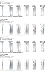
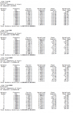
Anyway, besides the bias and cap issues, once biased, the bandwidth is normal, but it's not a good performer noise wise. If referred to a full output set at 21Vrms, the SNR is below 80db. Not so quiet. You must be having at least some noise coming out of those when there is no music playing.
And thd wise, not so good either. With the caps issue fixed and a bias of a little over 50mA in each output device, thd is fair at the low end, nothing great but not too bad, however, it does climb quite a bit with frequency. So this amp can't be giving super clean high end.
It takes 500mV peak at the input to drive it to nearly 30V peak at the output, for a little over 20Vrms, which would be about 50Wrms in an 8ohms load (resistive). This is with ideal 35V rail supplies, and it surely wouldn't be quite that nice in a real amp, with the rail sagging under load.
I think it doesn't need quite that much gain though. Most devices that can drive power amps these days have more headroom than that. So perhaps one way to "improve" it a little, would be to review the feedback ratio, and bring down the closed loop gain a little, which would leave a little more gain to reduce thd.
A line level device should be able to drive over 1V peak, easily, and more, so the amp doesn't need to be that sensitive. With a current gain of nearly 60 (more than 35db), that gain could easily be cut in half, so the amp could still be fully driven with some 1V peak, and at the same time thd would go down some.
The noise might even get a bit better as well.
Perhaps using those tone controls just boost the part of the spectrum that the amp has overly attenuated because of its limited bandwidth, but that doesn't fix anything.
Apparently you're not too picky or discerning when it comes to sound, so such an amp with limited abilities seems fine to you.
I just ran a sim of the version you're using, and there are quite a few things kind of wrong with it.
For starters, I can't see how it can be biased properly, with only 3 diodes and that resistor/trimmer in parallel with one of them, this just can't be enough to get enough bias current flowing in the outputs.
In this output stage, there are 4 junctions for the bias spreader to handle, and 3 diodes just can't quite cut it.
I could not get any bias flowing as it is, so moving the trimmer from in parallel with the diode in series with them does the job, so then it can be adjusted.
Then as I mentioned before, that input coupling cap just can't be right at just 100n, no matter how much boostrapping is used. The result is obvious in sims, with the roll off, although with an odd bump, starts much too high.
The boostrapping caps are also too small. One schematic calls for 10u for each, and the other calls for 47u. The larger values are of course better to widen the bandwidth at the bottom end, but barely enough, with a roll off still a little high.
I think the (C2) boostrapping cap on the ltp negative input should be at least 100u, and even better at 150u.
I tried that and only then, with an input coupling cap of 22u and the boostrapping cap at 100u, the bottom end no longer has that odd bump of extra gain before roll off, and it rolls off below 20hz normally.
The high end roll off is about ok though.
The filter caps on the front end rails are also rather small. One schematic calls for 10u. Not very much. The other calls for 47u, but I think that too is a bit small and I would at least double them.
That first sim you posted with that cap in parallel with the input, couldn't work as is. For one thing, that cap at the input wouldn't bother the sim, as long as no series resistance is added to the voltage source, so it wouldn't force any roll off, but in a real amp, if you have that cap, it would certainly cause some losses when combined with the previous device's output impedance (pre-amp...).
That cap just doesn't belong there. However there is no cap to make a real low pass input filter to limit the input signal bandwidth.
I found models for the db131, 2sa733 and tip31c/32c, so that's what I used to run it. The main difference between that sim and the schematic is the dual output pairs.
Anyway, besides the bias and cap issues, once biased, the bandwidth is normal, but it's not a good performer noise wise. If referred to a full output set at 21Vrms, the SNR is below 80db. Not so quiet. You must be having at least some noise coming out of those when there is no music playing.
And thd wise, not so good either. With the caps issue fixed and a bias of a little over 50mA in each output device, thd is fair at the low end, nothing great but not too bad, however, it does climb quite a bit with frequency. So this amp can't be giving super clean high end.
It takes 500mV peak at the input to drive it to nearly 30V peak at the output, for a little over 20Vrms, which would be about 50Wrms in an 8ohms load (resistive). This is with ideal 35V rail supplies, and it surely wouldn't be quite that nice in a real amp, with the rail sagging under load.
I think it doesn't need quite that much gain though. Most devices that can drive power amps these days have more headroom than that. So perhaps one way to "improve" it a little, would be to review the feedback ratio, and bring down the closed loop gain a little, which would leave a little more gain to reduce thd.
A line level device should be able to drive over 1V peak, easily, and more, so the amp doesn't need to be that sensitive. With a current gain of nearly 60 (more than 35db), that gain could easily be cut in half, so the amp could still be fully driven with some 1V peak, and at the same time thd would go down some.
The noise might even get a bit better as well.
after reading what you said...
i think the better way for me is build new ones...
stereo, better biased, better driver, better final transistor and also better frequency range...
i think i have been done with this circuit...
for better result, those things are too many much
now, i will make new one > APEX-H900 stereo
thank you very much...
I'm reviving this dormant thread to see if there is still some interest in some parts of the world for 3055/2955 based amps.
I was checking again if enough manufacturers were still making them, and although some of the few last manufacturers making those things are phasing them out, there are still a few left making them.
The one thing that could be an issue is among those few left to make them, there are sharp increases in unit pricing, which would render this enterprise pretty much useless.
But there may still be cheap enough sources out there, in some parts of the world.
I'm still interested in 3055 based amps, to see how much we can squeeze out of those old things.
The newer made 3055s have much higher Ft and even Vce0. Although we shouldn't try to rely too heavily on the higher Vce0, the higher Ft does make it suitable for "good enough" performance, for full range amps.
I was thinking about finishing up an amp based on a schematic from John Ellis, which is a "floating" (grounded) bridge, and it seems to be quite promising. It works great in simulations, with very nice performances, for a full range amp.
Being a grounded bridge, there is no need for a very high rail voltage, so the 3055s don't need to be pushed beyond their "standard" max Vce0. We can set the rails at 35V (idle), so with the losses and overhead, it should be at about the limit for Vce0 to those 3055s, knowing they very likely can handle much better, it should be quite safe.
I've done a lot of simulations on this possible amp, and it always worked very nicely and with very good performance for older devices.
Maybe a few more sims are needed to iron out some potential details and perhaps improve a little further, and then it's time for pcb design...
Anyone interested in such a thing?
Maybe a new thread dedicated to this build would be good.
Grounded Bridge, or not...?
Yes I'm all for a 2n3055 revisit, but I'd just go bridged with two or more pairs per side darlington driven.. Or how about a small class A pre driver stage swinging the 3055s in when needed...
It's purely a matter of bias!
The jlh class a for 4ohms then bridged is also a salivating potential but will only work well with proper 8 ohm speakers...
Last edited:
What I have in mind is the grounded bridge from John Ellis that we've done a lot of work on some time back.
His architecture works really nicely in simulations and with great performance, considering...
The configuration that I was thinking about is a 4 pairs of 3055/2955, with BD139/140 predrivers and MJ15030/31 drivers (for their power handling to drive 4 pairs easily).
The grounded bridge allows for a shitload of power with rails not over +-35V.
And for those really high power nerds, a grounded bridge can even be bridged as well. But that requires some more simulations and double checking that 4 pairs are sufficient.
The grounded bridge aimed at 8 ohms load, should also be able to handle 4 ohms, which is a really heavy load on each side of the bridge, being loaded at 2ohms. But 4 pairs can handle this, with a limit given by the protections.
The part that I was trying to figure out in the simulations is the protection. I couldn't get it to work exactly right.
It really must have protection, or it's too risky.
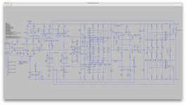
I'll post a recent sim schematic next, to give an idea...
His architecture works really nicely in simulations and with great performance, considering...
The configuration that I was thinking about is a 4 pairs of 3055/2955, with BD139/140 predrivers and MJ15030/31 drivers (for their power handling to drive 4 pairs easily).
The grounded bridge allows for a shitload of power with rails not over +-35V.
And for those really high power nerds, a grounded bridge can even be bridged as well. But that requires some more simulations and double checking that 4 pairs are sufficient.
The grounded bridge aimed at 8 ohms load, should also be able to handle 4 ohms, which is a really heavy load on each side of the bridge, being loaded at 2ohms. But 4 pairs can handle this, with a limit given by the protections.
The part that I was trying to figure out in the simulations is the protection. I couldn't get it to work exactly right.
It really must have protection, or it's too risky.
I'll post a recent sim schematic next, to give an idea...
Actually, while checking various suppliers that make 3055s, I found several still making them right now, and just in case, someone could always opt for the MJ15015/16 versions, which are recent, much faster, higher power, double Vce0, larger SOA, etc...
So in any case, such a build could be done for some time to come and I suspect, anywhere on this globe.
So in any case, such a build could be done for some time to come and I suspect, anywhere on this globe.
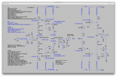
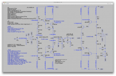
This is a slightly altered version of John Ellis' original architecture.
Nothing needs high Vce0. The power supply is simpler than usual, not even needing a center point for ground. So requires fewer parts.
The way I was thinking it would be built is minimizing as much as possible the "airwires", with as many parts as possible on a single pcb. With the fuses, big filter caps, diode bridges, etc... All on the same pcb, so only the wires from the main transformer are needed, and the input and output plugs mounted right on the pcb as well, so no wires needed there either...
This makes for a really simple and easy assembly build, while reducing risks of bad wiring to a minimum.
Even the heatsinks would be as simple as they can be, between the pcb and the TO3s, with only one junction to deal with, to not only make it simple but also reduce inefficiencies due to extra junctions that augment the thermal resistance.
Attachments
- Home
- Amplifiers
- Solid State
- Amplifier based on 2N3055