Hi,i assemble AX14P cuircuit but it is not start good and on the relay ther not goes suplly.so relay become not on,why and 15 volt supply comes on speaker
connect input GND to a psu star GND.
My pcb is ready to populate, expecting to complete it within this sunday.
Completed my First Apex Amplifier. I'm facing some problems that are:
1). I'm getting 0V across 0.33E resistor ( no variation with preset adjustment)
2). Sound is somewhat like mid is high causing bass to be low.
please help me to fix these problems, as i read lot about SR150's sound performance, but my SR150 is not sounding that much as expected.
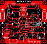
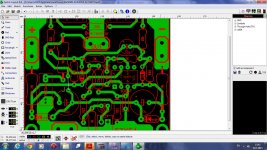
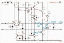
Not tested, please check for errors.
Sprint layout attached.
Nice work... you must add this jumper...
Regards
Attachments
Not tested, please check for errors.
Sprint layout attached.
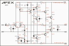
Atenzione!
Sanken SAP transisitors (with 5 pins) are no longer produced, they are obsolete. It is better to design pcb with new STD03N and STD03P transistors (with 4 pins)!
I make AX11 simulation and modified it.
Do you have pcb design for improved AX11?
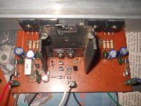
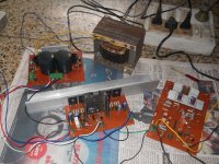
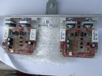
This is my second pair of finished AX11. PCB design is by Willy!
Attachments
Atenzione!
Sanken SAP transisitors (with 5 pins) are no longer produced, they are obsolete. It is better to design pcb with new STD03N and STD03P transistors (with 4 pins)!
Yes, and it is better to use OPA604 instead TL071.
Your fuses are blown.
EDIT; Looks like the 10R resistor is blown on the + side also. I see you relabeled the pins of the transistors. You can't do that. E is E, C is C and B is B. All you did was spin the transistor.
OK. Replaced all fuses & blown MJ15003.Checked all other Transistors & resistors. See attached. NOW have 274MV on output. +side draws 67.8MV across 10R in Series & -side draws 87.6mv across 10R in series.
Did NOT relabel anything on Orig Sch.
Attachments
Check the solder joint on the collector of the BC639. If you look at your schematic you will see that you have -40V on the collector yet +1 on the base of the BD140. Those should be connected and have the same voltage.
Attachments
Last edited:
Do you have pcb design for improved AX11?
This is my second pair of finished AX11. PCB design is by Willy!
I did not make pcb layout for my AX11 modification. Not yet.
This is simple amplifier, I think everyone can make the pcb design. Just take care of where the feedback point taking...
I did not make pcb layout for my AX11 modification. Not yet.
This is simple amplifier, I think everyone can make the pcb design. Just take care of where the feedback point taking...
A gift from me
")
Attachments
Hi Bimo,
Can you explain the reasons for the modifications you made? I'm interested.
I want to make it have high slew rate, then I change the compensation.
I like an amplifier that have high slew rate very much.
100W with OP and 2 outputs... just for fun.
Hi,
Lateral Mosfet output is possible ?
thanks
- Home
- Amplifiers
- Solid State
- 100W Ultimate Fidelity Amplifier