Hi James, I did not, I just checked it and its not grounded on the PCB. Strange, I have never seen this before. Is it possible that has caused the thing to go into meltdown?
I not sure how it would behave in such a situation but I'm suprised by the damage it suffered. Have you managed to get the boards working now?
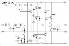
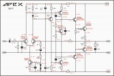
If you have 0V across the 0R33 resistors then you have no bias. Difficult to achieve without a trimmer on the VBE multiplier. I temporarily installed a 5k trimmer in place of the 4k7 resistor so I could adjust the bias. Then I measured the trimmer and installed the closest value resistor. In my case it was a 3k9. However, I built mine per the attached schematic. You used different transistors so you will likely end up with a different value.
It is possible that your offset may improve if you can get the bias up where it belongs.
There are not too many transistors. Maybe you could post the voltages you are getting. That would help us help you.
Blessings, Terry
It is possible that your offset may improve if you can get the bias up where it belongs.
There are not too many transistors. Maybe you could post the voltages you are getting. That would help us help you.
Blessings, Terry
Attachments
I not sure how it would behave in such a situation but I'm suprised by the damage it suffered. Have you managed to get the boards working now?
No where i live its a total pain getting semis and they are expensive. I am just going to look around for some outputs. I think the other channels outputs are not dead, but it still has the same problem as one with dead outputs before it lost its outputs if that makes sense
") So the other channel exhibits these symptoms:
So the other channel exhibits these symptoms:http://www.diyaudio.com/forums/soli...imate-fidelity-amplifier-103.html#post4377943
Hi, I started with the VX120 because I wanted to build a hybrid amplifier. The part with the tube I have separated from the amplifier. Comes next. The transistor amplifier running with +- 50V, 40mA bias, sine wave looks good, gain is 30.
Unfortunately, I have -1V offset.
Can anyone give a hint where I start with the adjustment?
Regards Olaf
Nice work, use 1k resistor in series with 1k pot instead 1k5 and set DC offset,
Regards
If you have 0V across the 0R33 resistors then you have no bias. Difficult to achieve without a trimmer on the VBE multiplier. I temporarily installed a 5k trimmer in place of the 4k7 resistor so I could adjust the bias. Then I measured the trimmer and installed the closest value resistor. In my case it was a 3k9. However, I built mine per the attached schematic. You used different transistors so you will likely end up with a different value.
It is possible that your offset may improve if you can get the bias up where it belongs.
There are not too many transistors. Maybe you could post the voltages you are getting. That would help us help you.
Blessings, Terry
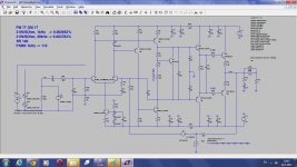
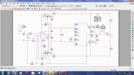
I make AX11 simulation and modified it.
Attachments
measuring in Vdc is not sensitive enough.Hi Terry,
I have tried to measure the Voltage across the .33R resistors i have installed & it is always 0V. If i put the gnd lead to gnd, i get same reading as the SPK Out. My MA meter also says 0.00ma on the V+ & V- tabs. Getting weirder..
You need to set your voltmeter to 2000mVdc, or preferably 200.0mVdc.
Attachments
Hi Mile, thanks for the advice. I will check this at weekend. To late this eveningNice work, use 1k resistor in series with 1k pot instead 1k5 and set DC offset,
Regards
regards Olaf
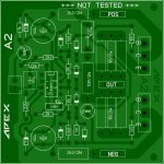
Just for fun - A2
if you want to test it, I can finalise this board at weekend. I can not build itself, have too many unfinished projects
regards olaf
Hi Terry,You have my attention. Layout?
if you want to test it, I can finalise this board at weekend. I can not build itself, have too many unfinished projects
regards olaf
Attachments
It is possible that your offset may improve if you can get the bias up where it belongs.
There are not too many transistors. Maybe you could post the voltages you are getting. That would help us help you.
Blessings, Terry
Terry,See attached for Voltages. ALL ref: to GND. Looks like i blew up another transistor i guess. I will get back to it in a couple days as i have eye surgery scheduled for tomorrow. Thanks to All
Rick
Attachments
Hi Terry,
if you want to test it, I can finalise this board at weekend. I can not build itself, have too many unfinished projects
regards olaf
+/-15V is ref to amp out not to gnd
Regards
Attachments

Yes, I have seen. Comes right in finished layout.+/-15V is ref to amp out not to gnd
Regards
Thanks.
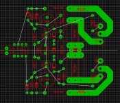
Layout A2
Hi, here is the layout for the A2. Would be nice if someone could check again. The layout is based on the circuit of post #5194. The Sprint-File is also uploaded.
I am very curious.
regards Olaf
Hi, here is the layout for the A2. Would be nice if someone could check again. The layout is based on the circuit of post #5194. The Sprint-File is also uploaded.
I am very curious.
regards Olaf
Attachments
Should base 4148 diodes be on heatsink, for like bias compensation?
Yes diodes must be on heatsink or use SAP15P and SAP15N in OS.
- Home
- Amplifiers
- Solid State
- 100W Ultimate Fidelity Amplifier