After the TVDD voltage mod, high frequencies opened a lot and much more detail now comes to my ears. But i still hear too much separation between high and mid frequencies, as if high frequencies were amplified sharply above a certain frequency: i suspect an high pass filter is a bit too high-cutting, after this mod.
What capacitor value should i increase to try to fix this (i.e. lower high pass filter frequency)? Maybe the small 390pF caps just after AK4399's output?
What capacitor value should i increase to try to fix this (i.e. lower high pass filter frequency)? Maybe the small 390pF caps just after AK4399's output?
No, you cannot set the pins, because the AK4399 is in serial (software) mode. Serial mode is mandatory because of dual mono setup. You must configure the DIF0-DIF2 bits of the register via software running on MCU.the AK4399 supports 32bit I2S compatible mode by having DIF0-DIF2 registry pin set to 1 but is it software only or we can gnd the pins?
This problem could be caused by many things, I wouldn't change the filter's cut-off (is around 120kHz), that's no solution. What version PCB do you have? If you have version 1, read my mod of analog +5V grounding. I also replaced the analog+digital +5V regulators to better ones. Try to improve psu / decoupling of output stage as well. To name a few possibilities...After the TVDD voltage mod, high frequencies opened a lot and much more detail now comes to my ears. But i still hear too much separation between high and mid frequencies, as if high frequencies were amplified sharply above a certain frequency: i suspect an high pass filter is a bit too high-cutting, after this mod.
What capacitor value should i increase to try to fix this (i.e. lower high pass filter frequency)? Maybe the small 390pF caps just after AK4399's output?
")
This problem could be caused by many things, I wouldn't change the filter's cut-off (is around 120kHz), that's no solution. What version PCB do you have? If you have version 1, read my mod of analog +5V grounding. I also replaced the analog+digital +5V regulators to better ones. Try to improve psu / decoupling of output stage as well. To name a few possibilities...
I have version 1 PCB.
Could you please specify better (nr. of post or quote) what mod are you talking about? This thread has become very long...
I would like to replace LT1086 regs with LT3080s (that are VERY good in my experience), but they are not directly swappable and i should modify the circuit that supports them - i could do it, but it would take too much time and effort now. Do you know other better low noise regs that could replace 1086 more easily?
By modifying decoupling capacitors of output stage, wouldn't i modify the second-order high-pass filter cutoff frequency anyway?
Luca72c: Nino is referring to MC7805 reg., they aren't directly swappable but if you check pin out of LT1085/6 which has from left to right GND-OUT-IN and MC7805 IN-GND-OUT it will be easy to swap, that also means you don't need resistor and cap around it, check schematics...
Luca72c: Nino is referring to MC7805 reg., they aren't directly swappable but if you check pin out of LT1085/6 which has from left to right GND-OUT-IN and MC7805 IN-GND-OUT it will be easy to swap, that also means you don't need resistor and cap around it, check schematics...
Sorry, maybe i have some problems in understanding english... you are telling me to replace LM7805 using LT1085/6, aren't you? You mean fixed-voltage 1085-5, i guess...
But LM7805 feeds only TVDD, AVDD, Toslink plug and XMOS board - according to DAC schematics. Do you think it could cause the sharp high frequency issue? It sounds strange to me... And using LT1085 would be a real improvement? If it's so critical for SQ, why not replacing it using an internal, separate low-noise 5V power supply like Diyinhk ones?
What about 5v grounding mod, anyway?
nope, I'm talking about those 3xLT1085/6, you can change them to MC7805 and yes I mean fixed 5V versions, don't touch LM7805 as this reg is not important for your mod, if you wanna change SQ than change your output stage either with more precise film caps or completely.
I didn't change 5V grounding as I have version 2 of this DAC
I didn't change 5V grounding as I have version 2 of this DAC
nope, I'm talking about those 3xLT1085/6, you can change them to MC7805 and yes I mean fixed 5V versions, don't touch LM7805 as this reg is not important for your mod, if you wanna change SQ than change your output stage either with more precise film caps or completely.
I didn't change 5V grounding as I have version 2 of this DAC
So you are talking about N3, N4 and N5, that feed AK4399 chips - that's right?
I agree they're critical for SQ, but MC7805s would be a substantial improvement then? These regs don't look so good to me... but i never used them... maybe i could make a big effort and find a way to use LT3080s...
What caps do you think i should change in output stage? You can refer to schematics' names, if you prefer.
Hi Luca72c
I was referring to the modification of the ground tracks here. IMO the LT1085 are not suitable in this application. I would replace them by a regulator with better RR and better impedance. I replaced them with Onsemi MC7805ACT.
Decoupling the +/- rails of the output stage won't change cut-off frequency of the filter. It's just to ensure a better transient response of the opamps. You have to experiment a bit in order to find the sound of your liking.
Nino
Hi Luca72c
I was referring to the modification of the ground tracks here. IMO the LT1085 are not suitable in this application. I would replace them by a regulator with better RR and better impedance. I replaced them with Onsemi MC7805ACT.
Decoupling the +/- rails of the output stage won't change cut-off frequency of the filter. It's just to ensure a better transient response of the opamps. You have to experiment a bit in order to find the sound of your liking.
Nino
Ok, i understand better, you were talking about opamps supply lines, not about opamps output lines. That's ok.
Modification of ground tracks should be good, but looking your pics i find it difficult to understand well... i can't find the backside trace to cut... also what 47uF caps should i replace with 470uF ones? I can't find any... maybe you meant the 100uF output caps?
More: by replacing LT1085s using MC7805s, adjustment caps (and resistors) have to be removed. So how does the ground tracks mod change? Their traces need to be cut the same? What do you mean with "bridge the pads where the adjustment cap was"? I should bridge the + and - capacitor's holes?
First you must decide what regulators you want. If you stick with the LT1085, you can upgrade the caps, as I suggested in my post. If you want to use MC7805, you need to modify it, because it has other pinout (see my post about MC7805 replacing LT1085).
About the grounding: It is best to connect the ground terminal of the regulator to the ground at the load, see my drawing. This way, the regulator senses the right ground potential. If the regulator was placed close to the load, this was no problem. But it isn't, so that's why I modified it. The wires carry the current from the load back to the psu ground. This is because I cut the traces from regulator ground to psu ground.
The 3rd trace on the backside goes from adjustment circuit to psu ground, middle regulator.
MC7805: You should bridge + an - holes of the 10u adjustment cap.
First you must decide what regulators you want. If you stick with the LT1085, you can upgrade the caps, as I suggested in my post. If you want to use MC7805, you need to modify it, because it has other pinout (see my post about MC7805 replacing LT1085).
About the grounding: It is best to connect the ground terminal of the regulator to the ground at the load, see my drawing. This way, the regulator senses the right ground potential. If the regulator was placed close to the load, this was no problem. But it isn't, so that's why I modified it. The wires carry the current from the load back to the psu ground. This is because I cut the traces from regulator ground to psu ground.
The 3rd trace on the backside goes from adjustment circuit to psu ground, middle regulator.
MC7805: You should bridge + an - holes of the 10u adjustment cap.
Thank you, i understand that. What i don't understand is: if we cut adjustment circuit ground traces, that are reg ground traces too, where will the regulator ground? In Vout positive line? That's strange...
How will its adjustment ground connect to load ground, like you show in the drawing attached to the post? Shouldn't we wire a way from adjustment capacitor negative pin, up to load ground? I see in the attached backside pic that you made some bridge from adjustment circuit to load ground, but you don't say anything about that in your post...
And what if we use MC7805ACT: the mod has to be made same way?
Thank you in advance for your patience, i'm a bit hard-headed...
No problem, it's important to understand the modification before doing it. The bridges on the backside you see on the picture: forget them, they are remains from another experiment....
Thank you in advance for your patience, i'm a bit hard-headed...
When the ground trace of the regulator is cut from psu, the original ground trace from that point is acting as exclusive ground (sense) trace for the reg. It only conducts a small current (denoted 'i' ) from the regulator's reference. It flows via the load-ground (the ground point from the 47u decoupling cap close to the DAC), back to psu, together with the main current 'I' (flowing from reg output, via load to load ground) . So the added wire conducts both currents (i + I) back to the psu, instead of the track that was cut (see 1st drawing). This way, the regulator senses ground potential at the load, instead of potential at the psu. (Because of the distance, the main current 'I' causes a voltage difference between load ground and psu ground.)
If you want to use a fixed regulator with different pinout, you have a ground pin instead of the adjustment pin (with resistors to ground). Best practice is to connect this ground pin also to the 'load ground' the same way, to get the best regulation.
No problem, it's important to understand the modification before doing it. The bridges on the backside you see on the picture: forget them, they are remains from another experiment.
When the ground trace of the regulator is cut from psu, the original ground trace from that point is acting as exclusive ground (sense) trace for the reg. It only conducts a small current (denoted 'i' ) from the regulator's reference. It flows via the load-ground (the ground point from the 47u decoupling cap close to the DAC), back to psu, together with the main current 'I' (flowing from reg output, via load to load ground) . So the added wire conducts both currents (i + I) back to the psu, instead of the track that was cut (see 1st drawing). This way, the regulator senses ground potential at the load, instead of potential at the psu. (Because of the distance, the main current 'I' causes a voltage difference between load ground and psu ground.)
If you want to use a fixed regulator with different pinout, you have a ground pin instead of the adjustment pin (with resistors to ground). Best practice is to connect this ground pin also to the 'load ground' the same way, to get the best regulation.
OK, i understand now. I ordered 3xMC7805s, if they sound so good it's okay to save some money...
N.B. i've added a proper capacitor to decouple 5V trace near to 3v3 chip: now Weiliang own XMOS is acting much better and its volume is back to normal - its SQ is lower than SPDIF, anyway. So i have to try feeding it with better 5V power to see if that can improve its SQ.
R2R comparison?
Is there anyone using this dac had experienced with R2R (or NOS) type dacs before? A brief comparison between these type of dacs and AKM's own sigma-delta architecture would be great idea. I wonder because these AKM dacs are so good but how much good comparing to a traditional R2R dac?
Is there anyone using this dac had experienced with R2R (or NOS) type dacs before? A brief comparison between these type of dacs and AKM's own sigma-delta architecture would be great idea. I wonder because these AKM dacs are so good but how much good comparing to a traditional R2R dac?
Dual AK4399 vs R2R
hi terranigma, I was able to evaluate in my system the Naim Dac ( 2X PCM1704k + 40BIT Sharc DSP ) having as source a CD transport, on 16bit/44.1Khz. The sound of dual AKM is much more spacious, with more sparkle in the highs, as the Naim sounds more 'physical' on medium and lows, having a thicker and maybe a bit neutral presentation. The comparison was made on classical and opera recordings, as well on very goof jazz recordings. The unmodified AKM kit sounds a little more exuberant, with better lateral rendition while Naim has more depth but lacks the panoramic feeling. The voices have more air on AKM, being a bit lighter, while on Naim they sound a bit more focused and heavy. You cannot criticize Naim too much if your taste is toward neutrality. If you want space and emotions, AKM is a delight to listen, even unmodified. I also compared the Matix Mini I, wich is a well engineered DAC for the money, build with dual AD1955. In balanced mode, without mods, this DAC excels in perfect natural timbre for voices and acoustic instruments, depth and excellent dynamic range. I had the chance to listen a lampized CD using dual AD1955, modified in a balanced tube output configuration, and the result was amazing except the sound stage width.
After all theses experiments, I prefer the AKM in my system, considering its sound character.
All these auditions were made only on red-book format.
I am going to modify my duak AK4399 with a SE tube buffer, and i will post my results here in February.
MY system consists in: 97dB two way 15'' bass reflex/SEOS15 horn loudspeaker with passive XO , EL156 + 6S45PI single ended valve amplifier, Audio Refinment CD Complete tweaked, DIY turntable with air suspended tangential tonearm + Lyra Delos cartrige, served by full valve MC preamplifier with input transformers.
Is there anyone using this dac had experienced with R2R (or NOS) type dacs before? A brief comparison between these type of dacs and AKM's own sigma-delta architecture would be great idea. I wonder because these AKM dacs are so good but how much good comparing to a traditional R2R dac?
hi terranigma, I was able to evaluate in my system the Naim Dac ( 2X PCM1704k + 40BIT Sharc DSP ) having as source a CD transport, on 16bit/44.1Khz. The sound of dual AKM is much more spacious, with more sparkle in the highs, as the Naim sounds more 'physical' on medium and lows, having a thicker and maybe a bit neutral presentation. The comparison was made on classical and opera recordings, as well on very goof jazz recordings. The unmodified AKM kit sounds a little more exuberant, with better lateral rendition while Naim has more depth but lacks the panoramic feeling. The voices have more air on AKM, being a bit lighter, while on Naim they sound a bit more focused and heavy. You cannot criticize Naim too much if your taste is toward neutrality. If you want space and emotions, AKM is a delight to listen, even unmodified. I also compared the Matix Mini I, wich is a well engineered DAC for the money, build with dual AD1955. In balanced mode, without mods, this DAC excels in perfect natural timbre for voices and acoustic instruments, depth and excellent dynamic range. I had the chance to listen a lampized CD using dual AD1955, modified in a balanced tube output configuration, and the result was amazing except the sound stage width.
After all theses experiments, I prefer the AKM in my system, considering its sound character.
All these auditions were made only on red-book format.
I am going to modify my duak AK4399 with a SE tube buffer, and i will post my results here in February.
MY system consists in: 97dB two way 15'' bass reflex/SEOS15 horn loudspeaker with passive XO , EL156 + 6S45PI single ended valve amplifier, Audio Refinment CD Complete tweaked, DIY turntable with air suspended tangential tonearm + Lyra Delos cartrige, served by full valve MC preamplifier with input transformers.
Thank you very much el156se. Your review is very encouraging. Your statement about airiness of AKM is highly valid according to my experience. If they ask me to a choose a single word to describe the sound character of AKM, I would say "airy" which is a very involving term to getting into music. My kit is modified and I'm using one transformer at each dac for balanced dual mono to single ended conversion. I found this configuration even better than the opamp configurations that I tried.
Last edited:
Happy New Year
Hi everybody
Happy 2015 to you all, with lots of DIY fun.
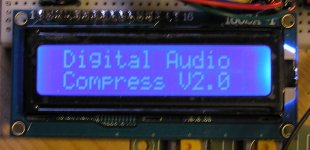
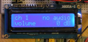
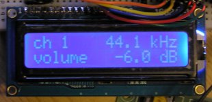
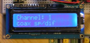
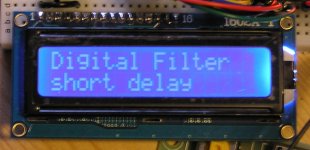
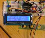
I finished controller software for Arduino Nano. It uses original LCD display and switches. Left switch is for selecting the function, middle is down, right is up. At start-up a welcome screen is displayed. See attached pictures.
Hi everybody
Happy 2015 to you all, with lots of DIY fun.
I finished controller software for Arduino Nano. It uses original LCD display and switches. Left switch is for selecting the function, middle is down, right is up. At start-up a welcome screen is displayed. See attached pictures.
Attachments
Hi everybody
Happy 2015 to you all, with lots of DIY fun.
I finished controller software for Arduino Nano. It uses original LCD display and switches. Left switch is for selecting the function, middle is down, right is up. At start-up a welcome screen is displayed. See attached pictures.
Hello Nino,
This is great. It is also fun to see going even further and fix something on some available design by respecting the DIY spirit.
Regards.
- Status
- This old topic is closed. If you want to reopen this topic, contact a moderator using the "Report Post" button.
- Home
- Source & Line
- Digital Line Level
- ebay:Weiliang Dual X2 AK4399 DAC with LCD