Ax-14 stereo done, next A-17. Thanks to Mr Mile for schematic & John Bali for Ax-20 layout(with little modification).
Regards.
Regards.
An externally hosted image should be here but it was not working when we last tested it.
An externally hosted image should be here but it was not working when we last tested it.
Ax-14 stereo done, next A-17. Thanks to Mr Mile for schematic & John Bali for Ax-20 layout(with little modification).
Regards.
Nice work, what about sound?
Regards
A17 running
My A17 works
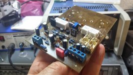
Ground-wiring is not optimal. I need a ground wire directly to the input to stop humming. I have the 4793/1837 replaced with 2SC2238 and 2SA968 - I had no other. Opamp is a NE5532, will be replaced later. The offset is 1.5 mV. Quiescent current is about 25mA. All components cool. All without any settings.
The sound is clear and neutral, close to the SR100. But I can not say anything yet. The test took less than 5 minutes.
I make a few measurements later in the day or evening, currently calls the family") .
.
regards
Olaf
edit: Humming is normal - forgotten the wire from PGND to SGND
My A17 works
Ground-wiring is not optimal. I need a ground wire directly to the input to stop humming. I have the 4793/1837 replaced with 2SC2238 and 2SA968 - I had no other. Opamp is a NE5532, will be replaced later. The offset is 1.5 mV. Quiescent current is about 25mA. All components cool. All without any settings.
The sound is clear and neutral, close to the SR100. But I can not say anything yet. The test took less than 5 minutes.
I make a few measurements later in the day or evening, currently calls the family
.regards
Olaf
edit: Humming is normal - forgotten the wire from PGND to SGND
Attachments
Last edited:
SoundsGreat
You should be fine using the parts number on the PCB they are the same as the schematic,
the input cap you don't really need a way too big cap there
and the reason I didn't make that cap "hifi sizes" is because it will make the PCB too big
Regards
Juan
You should be fine using the parts number on the PCB they are the same as the schematic,
the input cap you don't really need a way too big cap there
and the reason I didn't make that cap "hifi sizes" is because it will make the PCB too big
Regards
Juan
My A17 works
Ground-wiring is not optimal. I need a ground wire directly to the input to stop humming. I have the 4793/1837 replaced with 2SC2238 and 2SA968 - I had no other. Opamp is a NE5532, will be replaced later. The offset is 1.5 mV. Quiescent current is about 25mA. All components cool. All without any settings.
The sound is clear and neutral, close to the SR100. But I can not say anything yet. The test took less than 5 minutes.
I make a few measurements later in the day or evening, currently calls the family
regards
Olaf
edit: Humming is normal - forgotten the wire from PGND to SGND
Nice work and nice pcb, A17 is CFA amplifier and SR100 is VFA... sound CFA vs VFA
Regards
Ha ha ha was something reminds meNice work and nice pcb, A17 is CFA amplifier and SR100 is VFA... sound CFA vs VFA
Regards
Hi,
Ok got it much obliged,I saw there were a few differences hence asked,for example instead of 1817 there is 15032 and such. Anyways will follow the PCB,Additionally will try some more to see which sounds good.
Btw in your views,which sounds better the 5200 version or 15003 ??
Regarding the Transformer,is 45-0-45V 5A (450VA) will do or should I go for 8A (720VA) ?? I need order them so asking,I want the best and Optimal so kindly suggest the same.
Also what bout the Slew rate of this ?? and Max Current ( for transient loads) ?
Regards.
You should be fine using the parts number on the PCB they are the same as the schematic,
the input cap you don't really need a way too big cap there
and the reason I didn't make that cap "hifi sizes" is because it will make the PCB too big
Regards
Juan
Ok got it much obliged,I saw there were a few differences hence asked,for example instead of 1817 there is 15032 and such. Anyways will follow the PCB,Additionally will try some more to see which sounds good.
Btw in your views,which sounds better the 5200 version or 15003 ??
Regarding the Transformer,is 45-0-45V 5A (450VA) will do or should I go for 8A (720VA) ?? I need order them so asking,I want the best and Optimal so kindly suggest the same.
Also what bout the Slew rate of this ?? and Max Current ( for transient loads) ?
Regards.
Last edited:
Nice work, what about sound?
Regards
Great Sound Mr Mile. Thanx.
Mr. Mile , I had to replace the transistor 2sc4793 & sa1837 with TIP41 and 42 , the final use 2SC2577 and 2SA1102 ( 60watt ) the results tend to bass voice , I give 40v dc voltage and bias ( B to B ) 1000mv / 1v . If there is any advice I receive . Thank you .
Mr. Mile , I have a lot of NOS transistors , 2sa103 , 2sb175 , 2sa102 , 2sb175 , 2sb176 , BC376 , s8550 , s8050 . Is there amplifier can I make from one of these transistors ???
Sorry , I do not have much experience about amplifiers .
(Sorry for Bad english)
Thanks for the advice of Mr. Mile .
https://imageshack.com/i/eyCiWCHHj
https://imageshack.com/i/iqfOTKZCj
NE5532 is not good for A17 (bad offset) but 1,5mV is not so bad.
Hi, yes but was only one type I had at the moment.
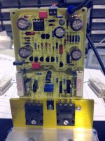
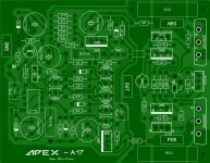
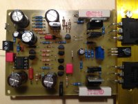
Here are a few photos and layout. The dimensions are 90x70mm.
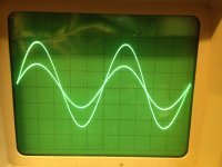
The sinus is 0.5Vpp and 10Vpp at 20kHz. Operating voltage is + -36V DC. Bias is 50mA (all I could set with this setup), offset then is 4mV after 15 minutes when all is warm.
Very nice amplifier - thank you Mile.
regards Olaf
Attachments
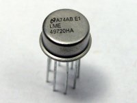
Can i use opa2134 or LM4562 instead NJM2068???
Regards
Use LM4562 metal TO-99
Attachments
Hi, yes but was only one type I had at the moment.
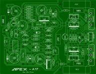
Here are a few photos and layout. The dimensions are 90x70mm.
The sinus is 0.5Vpp and 10Vpp at 20kHz. Operating voltage is + -36V DC. Bias is 50mA (all I could set with this setup), offset then is 4mV after 15 minutes when all is warm.
Very nice amplifier - thank you Mile.
regards Olaf
This amplifier promises superior audio fidelity,
Regards
apexaudio
Nice new CFA amps, just on time on winter evenings to solder them !!
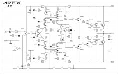
I have few questions, the A9 and AX9 they have 22R resitor at the NFB ground end, looks like it should be higher value to decrease gain a bit ??
The NFB is divided (A9) GND--22--470--1500--OUT,
what is the advantage of dividing NFB with middle 470R resistor (bit bigger part is injected into the second stage) ?
The marantz PM7001KI is using a jumper in this point.
The TL072 will be any good to start with ?? (I have only NE5552 and TL072 opamps in stock)
Sorry if my questions are a bit stupid.
thanks
Regards Peter
Nice new CFA amps, just on time on winter evenings to solder them !!
I have few questions, the A9 and AX9 they have 22R resitor at the NFB ground end, looks like it should be higher value to decrease gain a bit ??
The NFB is divided (A9) GND--22--470--1500--OUT,
what is the advantage of dividing NFB with middle 470R resistor (bit bigger part is injected into the second stage) ?
The marantz PM7001KI is using a jumper in this point.
The TL072 will be any good to start with ?? (I have only NE5552 and TL072 opamps in stock)
Sorry if my questions are a bit stupid.
thanks
Regards Peter
apexaudio
Nice new CFA amps, just on time on winter evenings to solder them !!
I have few questions, the A9 and AX9 they have 22R resitor at the NFB ground end, looks like it should be higher value to decrease gain a bit ??
The NFB is divided (A9) GND--22--470--1500--OUT,
what is the advantage of dividing NFB with middle 470R resistor (bit bigger part is injected into the second stage) ?
The marantz PM7001KI is using a jumper in this point.
The TL072 will be any good to start with ?? (I have only NE5552 and TL072 opamps in stock)
Sorry if my questions are a bit stupid.
thanks
Regards Peter
A9 and AX9 are simple CFA amps for use without preamp only volume pot on input, for AX17 there will be preamp... increase 22R to 47R or 100R to decrease gain.
Dividing NFB is for stability and some other reasons... with jumper in mid point OP work only as dc servo and ac buffer like in B500, use jumper with TL072 or NE5532.
Regards
Last edited:

- Home
- Amplifiers
- Solid State
- 100W Ultimate Fidelity Amplifier