So which is it?
degeneration solves all the parameters variations and selecting/matching is NOT required
or
selecting/matching is required in some locations to bring operating parameters within tolerable range.
To comment on that part, my experience beyond the practical terms for this phono circuit, suggests that degeneration helps with stages gain and thermal stability (gain is moot to tightly control if under loop feedback circuitry) while full matching helps in THD % and its trend uniformity between channels in mirrored and differential circuits as well as in situations where sweet spot cancellation techniques are employed, especially when to avoid various trimmers.
 Good luck!
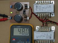
P.S. I was thinking of maybe adding a small board for the guide's supply at the time of latecomers boards round just for visual synergy but I want to know that enough members have firstly followed and if happy with it and its grounding scheme works in many systems alike. Because the PSU part is contentious I am not sure if to bother though. Your builds will indicate.
Hi Salas,
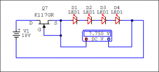
I measured all (GB minikit) LEDs and all Vfs are around 1.92V with 1.62K resistor in series based on 9V battery.
How did you got 7.75v and 5.8V? I might didn't get it right. Please see my setup drawing.
Hi Salas im also struggling to reach 7,75v on a quartet,
i have about 150leds and only a a few are as high as 1,91v (adds up to 7,64V)
im using a 9v battery and about 1,4Kohm
ill do a test with a string of 4, and test the total, what size of resistor / what current should i test with?
Per
Hi Salas im also struggling to reach 7,75v on a quartet,
i have about 150leds and only a a few are as high as 1,91v (adds up to 7,64V)
im using a 9v battery and about 1,4Kohm
ill do a test with a string of 4, and test the total, what size of resistor / what current should i test with?
Per
Having same Vftotal quartets and triplets is priority to absolute value because it keeps the cascode voltage bias the same between channels. Don't worry much for guide's refVftot when in the close neighborhood if you can't reach it or just mix a green LED but its not the best thing to do aesthetically.
Test for 4-5mA current. Itest=(Vtest-Vftot)/R
Use 15V-20V. You can also use the K117 Q7 prepared for the board in IDSS mode instead of a resistor to feed them current. That will be even closer to the specific in circuit conditions. If without lab PSU stack 2x 9V batteries up.
Attachments
Thanks Salas. Does that mean a total Vf of quartet of leds of 7.6V is acceptable as long as both sides are matched?.
Quan
Yes you can use 7.6V matched between channels. Its we got VR2X & VR1 to still bias right in all somewhat different cases.
Having same Vftotal quartets and triplets is priority to absolute value because it keeps the cascode voltage bias the same between channels. Don't worry much for guide's refVftot when in the close neighborhood if you can't reach it or just mix a green LED but its not the best thing to do aesthetically.
Test for 4-5mA current. Itest=(Vtest-Vftot)/R
Use 15V-20V. You can also use the K117 Q7 prepared for the board in IDSS mode instead of a resistor to feed them current. That will be even closer to the specific in circuit conditions. If without lab PSU stack 2x 9V batteries up.
Thanks ,
will play with leds tonight and see what i end up with.
Per
Great. Then leds are sorted.Yes you can use 7.6V matched between channels. Its we got VR2X & VR1 to still bias right in all somewhat different cases.
Quan
Super Vfw green leds these must be.... anyway, with the low current we are using here, IMO best option would be orange/yellow leds.green @ 2.85Vf must be quite unusual.
Mine measure similar to red, but on average slightly higher than red.
I did have some very low voltage red (1.55Vf to 1.6Vf), but unfortunately have used them all up.
I have used 7,5 volts with good results.
- Home
- Source & Line
- Analogue Source
- Simplistic NJFET RIAA