Are any builders using more fancy film and foil or botique caps for the input cap, and if so was there a worthwhile improvement ? I'm getting closer to finishing mine and was just wondering.
Thanks,
PJN
Clarity cap SA. Worthwhile improvement = yes.
niss_man, have you compared the Clarity Cap SA to no cap at all (DC connected)?
Nope. I will let other experimenters do that.
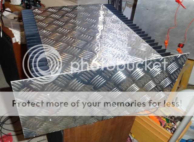
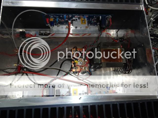
Well I finished it. Well sort of. I should probably make the changes OS suggested. It sounds lovely like it is. The case ended up larger than needed because of the size of the heatsinks I had and the length of the PCB's. I think if I knew how to design PCB's I would design it to have three outputs per side rather than in a row to shorten it up. My heatsinks get barely warm. Could have done with half the size easily. It may find it's way to a smaller case some day. Anyway, here it is in the 5U case. a couple pics with my son's Hafler sitting on top for scale.


Your PA is enormous, still4given, and looks good. If you PS voltage is not much higher than 125V (- to +) then you could use BAS45a ostripper recommended as it has very low reverse current. Actually, some of these diodes are likely to have higher reverse voltage than the nominal 125V by 10V or so. Stochino uses many antisaturation diodes in his amp and he recommended that builders select diodes with reverse voltage higher than their nominal maximum by over 10V and every second diode from those recommended had that voltage higher than their nominal maximum.
You may also build a regulates PS for LTP and VAS with rails roughly +/-5V higher/lower than the output PS. It will make some difference. Just get a 2x50V 80VA toroid.
cheers,
You may also build a regulates PS for LTP and VAS with rails roughly +/-5V higher/lower than the output PS. It will make some difference. Just get a 2x50V 80VA toroid.
cheers,
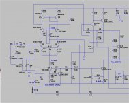
For those who would like to use separate regulated PS for LTP and VAS. With 2x50V or so it can give nicely regulated output up to +/-68V. Tip33-zener-resistors form a protection circuit for regulators and prvent the maximum input-output volatege for regulators to be exceeded.
cheers,
cheers,
Attachments
Last edited:
For those who would like to use separate regulated PS for LTP and VAS. With 2x50V or so it can give nicely regulated output up to +/-68V. Tip33-zener-resistors form a protection circuit for regulators and prvent the maximum input-output volatege for regulators to be exceeded.
cheers,
One would "lift" R32 and R33 (omit them) and solder a pin (wire wrap post) on the blue/ red LED side of those resistor pads. This is where you would connect the higher rail (separate PS).
A 5-10R (1/2w) fusible resistor would be the best safety component used between that supply and the LTP/VAS.
This is the present form of the first "badger" (mine) - 60-0-60VDC for the drivers/OPS and 68-0-68VDC for the LTP/VAS.
The Nikko amp's (badger replaced the nikko) toroid secondaries are 42-0-42 and 50-0-50VAC...
OS
Last edited:
Does the PS for the front end have to be regulated?
Nope. mine isn't.
OS
There are no complete kits for the HB that I'm aware. There are a couple of BOMs in this or another thread. Also PCBs are available from the DIY store. I'm going to start building mine as soon as my basement and workshop are done. Just moved into a new home. Too much else to do....I haven't followed this thread for a while.
Is there a HB kit, with pcb and components ?
Are there any other sources for the pcb ?
Thanks
fs
Rick
Rick - thanks
Its not easy buying things from USA, nearly always gets taxed and a huge handling fee from the courier/postal services. A 40USD item will get taxed 8USD (which I don't mind) but the handling is around 20USD. Whereas items from asia don't seem get charged at all, as they seem to report a nominal value without asking, where many of your compatriots prefer to report the full value.
Its not easy buying things from USA, nearly always gets taxed and a huge handling fee from the courier/postal services. A 40USD item will get taxed 8USD (which I don't mind) but the handling is around 20USD. Whereas items from asia don't seem get charged at all, as they seem to report a nominal value without asking, where many of your compatriots prefer to report the full value.
Instability upon bias change
Greetings all,
I have been lurking here for a while, but this is my first post. I have built up a HoneyBadger system, pretty similar to JoJo's: Soft-start, Antek AN-8445, 2xUniversal PSU (1 per channel). This is my first amp build, but please don't hold that against me
Upon firing up my first channel (with the bias, offset and ccs resistors set as per the build guide) all seems well... no smoke escaping, led's nicely lit. My offset was a couple of mV. The TP1/TP2 bias measurement was sitting around 0.1 mV. I measure around 7.90 V across R14 (ca. 3.6 mA). I have noticed the heatsink for Q10/11/12 is a little warm, but the output stage transistors are cool. I notice R50 is ever so slightly warm. I have nothing attached at the outputs, apart from a DMM if I'm measuring offset.
Anyway, as I slowly increase the bias all seems well until I hit around 8.2 mV at which point it sky-rockets to closer to 100 mV (and I proceed to turn the unit off). Less than a quarter turn back, and with the unit switched back on and it seems happy again at around 8 mV. If I don't turn the unit off after it has sky-rocketed (and instead try to wind down the bias) even at max resistance of R30 (500R) the bias voltage remains at around 30 mV, until I switch it off and on again, at which point it's back to 0 mV. Sorry about all the information... I figure more is better.
Where can I look to diagnose this instability? I have recently acquired a tired old D61a scope, but that needs some love before it can be of much use. Perhaps this should be my first priority?
Regards
Scott
R50 slightly warm = possible instability (oscillation). It should be cold.
I had this happen once when I forgot to set the cascode. Check to make sure you have the C-R or C-Z jumper in (or test the bases Q3/Q4 for a steady voltage,whether it is the Zener or resistive divider).
Also, what input devices are you using. Some ultra high gain Zetex models (simulated) have required extra degeneration (R15/16 higher value) for normal
operation.
Ground the heatsinks ! Check the Q9/Q10 - C7/C8 area, make sure it is right. Also ... you might try
increasing R24 (TMC feedback) from 820R to 1-1.5K.
fire up the second channel , this will determine if it is a mistake or not.
Show some detailed photo(s).
OS
Last edited:
R50 slightly warm = possible instability (oscillation). It should be cold.
I had this happen once when I forgot to set the cascode. Check to make sure you have the C-R or C-Z jumper in (or test the bases Q3/Q4 for a steady voltage,whether it is the Zener or resistive divider).
Also, what input devices are you using. Some ultra high gain Zetex models (simulated) have required extra degeneration (R15/16 higher value) for normal
operation.
Ground the heatsinks ! Check the Q9/Q10 - C7/C8 area. Also ... you might try
increasing R24 (TMC feedback) to 1-1.5K.
Show some detailed photo(s).
OS
Thanks for the quick reply!
The cascode is set using a Zener reference (C-Z jumper). The voltage across the Zener is 14.34 V.
My chassis heatsink is connected to ground, but the aluminium plate at Q10 to Q12 is not. Should it be?
Everything seems in order in the Q9/Q10 - C7/C8 area and I can't find any shorts. I have tried increasing the TMC feedback resistor to 1k. This has the same effect as before, except I can get to very slightly higher bias voltage before the instability, around 8.8 mV.
I have used MPSA18 transistors for Q1 and Q2. Would you suggest increasing R14/15 in this case? If so, how much higher? 150R? 200R? 1K? Would it be easier to swap these transistors out?
I fired up the second channel and I think it's the same story, but I'm not too sure as I left it on a little longer (at higher bias) and it fried my fuses and "safety" resistors (both R53 and R54). These flameproof 22R resistors just got flamed and now measure around 23k! It seemed happy for several minutes before I touched the bias. I guess I'll try and get the first one going properly before I come back to the second one.
Thanks, I really appreciate the help.
Scott
MPSA18= Hfe min 500 and max 1500.
Too bad that they do not have gain groups - no way to tell if you have 500 or 1500+ ..
KSC1845(f) = Hfe 300/600
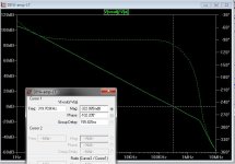
I plugged in a Zetex 1048a (below-) , the highest gain model I had (Hfe 1200+).
Yes , the phase margin was "on the edge" (possible instability).
If you have Hfe 1200 (or even 1500) MPSA18 , increase R14-R15 to 220R.
This brings the phase margin back to 78deg - stable , (see below.. 180-102deg.=78).
Also shown below is the high gain zetex models with the resistor changes.
I ran this with the global feedback resistor (R6/R3 - gain) at 22k/27K/and 33K - good.
I tried to get my amp to oscillate when I first built it. Lowered the Q10 miller cap to 47p (nope-all was good). When I lowered R14/15 to 10R (misread the resistors) , I really oscillated and could not set the bias.
Totally SMOKED the zoble resistor !! This was with standard KSC1845(F-Hfe300-600).
PS - you might want to consider using the ksc1845(f) or BC546 BC547(a-b) as LTP.
Also , if the current mirror (Q5-Q6) has uber high gain ... this will have the same effect - something to consider.
OS
Too bad that they do not have gain groups - no way to tell if you have 500 or 1500+
..KSC1845(f) = Hfe 300/600
I plugged in a Zetex 1048a (below-) , the highest gain model I had (Hfe 1200+).
Yes , the phase margin was "on the edge" (possible instability).
If you have Hfe 1200 (or even 1500) MPSA18 , increase R14-R15 to 220R.
This brings the phase margin back to 78deg - stable , (see below.. 180-102deg.=78).
Also shown below is the high gain zetex models with the resistor changes.
I ran this with the global feedback resistor (R6/R3 - gain) at 22k/27K/and 33K - good.
I tried to get my amp to oscillate when I first built it. Lowered the Q10 miller cap to 47p (nope-all was good). When I lowered R14/15 to 10R (misread the resistors) , I really oscillated and could not set the bias.
Totally SMOKED the zoble resistor !! This was with standard KSC1845(F-Hfe300-600).
PS - you might want to consider using the ksc1845(f) or BC546 BC547(a-b) as LTP.
Also , if the current mirror (Q5-Q6) has uber high gain ... this will have the same effect - something to consider.
OS
Attachments
Last edited:
This kind of oscillations is one of the worst things to happen as it is difficult to locate its source and the source may be in the quality of some parts including output transistors. I encountered the same problem with "diamond" amp. By the time we got a clue (a friend of mine assisted me) board was almost ruined from desoldering and soldering so I gve up before checking the most recent solution (worked in simulations).
I know very little about TMC but I noticed that in some amps a small antioscillation resistor is added. In HB it would go from C7/base Q9 to R5/R6 joint - C7-additional R are parallel to R6.
In LTP one can also try 100pF plus 1k between collectors of Q3-Q4 if problem is there. Then driver transistors (q14-15) and their caps.
cheers,
- Home
- Amplifiers
- Solid State
- diyAB Amp The "Honey Badger" build thread