As far as using the cap multiplier , you can split the CRC on the badger (remove R32/33)
and run the small signal section (C11/15) of the amp with the multiplier.
The output and drivers would really like to see some "real farad's" (20-40Kuf per amplifier).
Just a thought.
and run the small signal section (C11/15) of the amp with the multiplier.
The output and drivers would really like to see some "real farad's" (20-40Kuf per amplifier).
Just a thought.
As far as using the cap multiplier , you can split the CRC on the badger (remove R32/33)
and run the small signal section (C11/15) of the amp with the multiplier.
The output and drivers would really like to see some "real farad's" (20-40Kuf per amplifier).
Just a thought.
Thank OS,
I'll take your advice on the above changes. After listening to if a good part of the day, it sounds pretty good but it has just a touch too much sizzle on the highs. not sure if that is oscillation I'm hearing but cymbals and that "air" that everyone likes to add to the vocals now-a-days have a little too much sizzle. Maybe the changes you mentioned will take care of that. I do want to lower the gain a little. That might help with that too.
I happen to have a nice hefty Haffler e-core transformer that puts out +/-65Vdc. I may give that a try. I'll have to do CRC with it though because that cap multiplier won't go that high. I've got a few caps I could use for that.
Thanks again, Terry
When I look at the foil on the bottom of the board, OV TP is connected to the SPK GND which is where I have the main ground wire attached. I don't actually have a chassis right now, just a heatsink.
Right, I couldn't tell from your first pic.
I'll take your advice on the above changes. After listening to if a good part of the day, it sounds pretty good but it has just a touch too much sizzle on the highs. not sure if that is oscillation I'm hearing but cymbals and that "air" that everyone likes to add to the vocals now-a-days have a little too much sizzle. Maybe the changes you mentioned will take care of that. I do want to lower the gain a little. That might help with that too.
Could you try an LC cap?
Dude, I should have tried the higher voltage before. I just hooked up the Hafler tranny and only a couple 10Kuf caps that I had handy and there is a world of difference. It even tamed the high end. It's holding at about +/-63V rails while playing. Probably drop another volt for the CRC. Can't wait to hear it with some proper filtering. Looks like I have a little work to do and then build a case. I think this might be one of my favorites.
Thanks guys!
Thanks guys!
Could you explain the purpose of R53/54 further thanks Os? When I had issues in the early stages of mine years ago, one of the fuses blew and all the musical current flowed through the resistor as a result. There was no sign of the fuse blowing as the music was still playing fine. This made the resistor/amp catch on fire. This is the reason R53/54 were removed on my amp as I think it's a safety hazard with them still in place.Good job!
After refining some of the parameter's as I highlighted above - the little 'bugs" will go away.
I'm going to use lead spacers (below-"ceramic resistor lead spacer") for my R53/54 just to be safe.
You could go for 60-65V rails and have a concert with those heatsinks -(200W+ peaks )!
OS
Regards
Simon
Could you explain the purpose of R53/54 further thanks Os? When I had issues in the early stages of mine years ago, one of the fuses blew and all the musical current flowed through the resistor as a result. There was no sign of the fuse blowing as the music was still playing fine. This made the resistor/amp catch on fire. This is the reason R53/54 were removed on my amp as I think it's a safety hazard with them still in place.
Regards
Simon
I've got to say I was thinking the same thing. I'm not very happy about the big black spot on my brand new boards. Does this amp go DC on the output if you lose a rail? If not, I think I'll clip those resistors off.
On another note. I just noticed that I have a 63V cap in C13. Not sure why I did that when all the others are 100V. Probably something I had in the parts bin. I think I had better change that one out if I use the Hafler transformer.
I'm glad to hear that, as I'm building 63v rails too.
Someone with more knowledge than me could easily test the DC question using the DC speaker protection board. I built it, and I'm fine with hooking up mains, but not comfortable enough to start my own "what if" scenarios (not with what I spent on caps at least") .
.
Terry, just for my education, I was under the impression that CRC filtering wasn't needed for an A/B amp?
Someone with more knowledge than me could easily test the DC question using the DC speaker protection board. I built it, and I'm fine with hooking up mains, but not comfortable enough to start my own "what if" scenarios (not with what I spent on caps at least
.Terry, just for my education, I was under the impression that CRC filtering wasn't needed for an A/B amp?
Here is the story of the rail fuse resistors ...
(post 18) - http://www.diyaudio.com/forums/solid-state/192431-diyab-amp-honey-badger-2.html#post2636524
They can be used to measure quiescent current. They will burn if not omitted (flameproof ??).
I have blown rail fuses (my amp has no rail fuse resistors) no DC...
But with an amp of this scale, a DC protect would be good IF you are not offended by an output relay.
The best alternative ... ESP - MOSFET Solid State Relays
... several members have built these and integrated them with turn-on delay and DC detect . This is the way mine will be (still collecting parts/$$$).
Glad 60V rails gave much pleasure!!
OS
Dude, I should have tried the higher voltage before. I just hooked up the Hafler tranny and only a couple 10Kuf caps that I had handy and there is a world of difference. It even tamed the high end. It's holding at about +/-63V rails while playing. Probably drop another volt for the CRC. Can't wait to hear it with some proper filtering. Looks like I have a little work to do and then build a case. I think this might be one of my favorites.
Thanks guys!
Too bad I am not as financially secure as I would like to be.
My (future sub amp) will be 40VDC rails and MJE340/50.
I would build my mains (L/R) as 60VDC units and document the "fine tuning" of both.
This amp CAN be scaled down to lower voltages and retain the same sonics and electrical characteristics as a 60VDC version.
R11-13 and R18-19 can be scaled down by a third in value to maintain current in the dividers.
Both the small signal area and the VAS should remain constant (current sources) regardless of voltage. Mine plays music down to about 15V rails before distorting at shutdown (low volume).
A main CRC is not essential (amp already has a small CRC built in) , but it can not hurt. (CRC + a CRC = a few more db PSRR
)OS
I didn't realize there was already a crc in the amp. Maybe I'll just stack some caps in a row then and be done with it. Actually, after I made sure all was settled, I disconnected from the variac and plugged straight into the wall and ended up with +/-67V rails. That amp didn't hick-up, just purred along. I felt everything I could touch and no heat anywhere. Even the angle I have bolted across the outputs was just warm and that is with TP1& TP2 set to 30mv. I do have C15 sitting there at 63V that I will have to change but everything else seems fine. I haven't tried a 4R load yet but will after I get the PS set up. I will try bringing it up on power with one rail disconnect and see what happens at the output. It the DC isn't too bad I'll snip off R53 & R54.
It actually played fine at +/-37Vdc rails. I was very tempted to leave it there. I really only tried the Hafler because of what you said. I'm glad I did. The extra umph gave it a little better sound stage and tightened up the bass a bit. I would imagine if you were planning to run at the lower voltage you might want to leave off a pair of outputs.
Thanks OS!
Blessings, Terry
I didn't realize there was already a crc in the amp. Maybe I'll just stack some caps in a row then and be done with it. Actually, after I made sure all was settled, I disconnected from the variac and plugged straight into the wall and ended up with +/-67V rails. That amp didn't hick-up, just purred along. I felt everything I could touch and no heat anywhere. Even the angle I have bolted across the outputs was just warm and that is with TP1& TP2 set to 30mv. I do have C15 sitting there at 63V that I will have to change but everything else seems fine. I haven't tried a 4R load yet but will after I get the PS set up. I will try bringing it up on power with one rail disconnect and see what happens at the output. It the DC isn't too bad I'll snip off R53 & R54.
It actually played fine at +/-37Vdc rails. I was very tempted to leave it there. I really only tried the Hafler because of what you said. I'm glad I did. The extra umph gave it a little better sound stage and tightened up the bass a bit. I would imagine if you were planning to run at the lower voltage you might want to leave off a pair of outputs.
Thanks OS!
Blessings, Terry
Glad everything worked out.
Look below to see what you got me onto ... looks familiar ,aye.
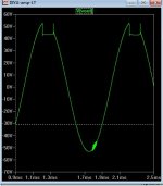
Anyone who says the simulator ... (with accurate models -Andy C's + B.Cordell's) can't predict the real world is dead wrong.
Manufacturer models and standard LT spice models do not show this "quasi saturation" variable .... So this is a issue that might plague
many a DIYA amp (most with this topology).
Glen Klienschmidt (GK - former DIYA member) solved the "sticking" problem somewhere in the "frugalamp" thread , I will find the solution. Why not go for perfection.
As this amp is ... at 63+VDC , you would have to exceed 110V P-P(below) to create this condition - highly unlikely. That's one hell of a peak , and even if you do that parasitic oscillation would be mostly absorbed by the Zoble /output inductor.
My present badger uses a 70V rail for the LTP/VAS. That is why I could not recreate this on mine - the output stage clips way before the VAS does.
I will explore this "anal" pursuit for perfection in the Badger discussion thread -
A good healthy dose of "mental masterbation". I think it just requires a couple of strategically placed high speed diodes (another option with minimal rework).
PS - My low voltage amp will have all 3 pairs - needs to run a 2R subwoofer. A lower voltage Badger just needs to have lower gain
to avoid the "hard clip scenario" + the above recommendations in post #589 .
OS
Attachments
Last edited:
Wow, how about that! At least I know it wasn't something I have wrong. I figured it probably wasn't something that would matter all that much as it happens just as the amp clips and we rarely run that hard. Still it will be good to find a cure. I hope you stay with it. I didn't try it with the bigger Tx. I just let it play. This is a very pleasant sounding amp. I'll get some caps ganged together this week and put a case together. I think I'm going to like this amp.
Wow, how about that! At least I know it wasn't something I have wrong. I figured it probably wasn't something that would matter all that much as it happens just as the amp clips and we rarely run that hard. Still it will be good to find a cure. I hope you stay with it. I didn't try it with the bigger Tx. I just let it play. This is a very pleasant sounding amp. I'll get some caps ganged together this week and put a case together. I think I'm going to like this amp.
I have the "old man" badger. 2 1/2 years .. parties , running subs , general abuse.
I'm now running some quality Mission 763i's with Vifa tweeters and new woofers. Man , I can hear some stunning detail with better speakers. After
junk sony (general purpose) speakers ... wow!
I haven't used my DIYA boards yet , I think they are far superior to my prototypes layout. Can't wait...
This amp (even my prototype) sounds wonderful. It's just a very "transparent" amp , it will expose a good source as well as a poor source/recording. It adds nothing - as it should , that's why we have DSP (digital signal processing)!
Enjoy !!
OS
Hi os - would I need to make any changes for running at 45-50v ? Also what's the lowest I can test at on a bench supply ? Cheers . Almost built one....
45-65V is what the present design is optimized for.
I just suggested changing the gain to suit the maximum
output level of the amp.
(and the source - preamp or direct PC soundcard)
R3/6 = 22k
22k for 65V rails - 3.6V p-p in for 102V p-p out
22K for 50V rails - 3V p-p in for 80V p-p out
The amp will work at 20-0-20VDC, it will just clip at a much lower level.
As I stated a few posts back , the badger's current sources and the sound
are not affected until the amp goes below 15VDC at the rails. Lower than this , the gain of the amp is too high for the supply.
OS
modified Stochino mk Ia
Sorry, that trick with that clamping diode would have worked if LTP-VAS were upside down. Then Q10 would be the lower VAS and this diode would connect its collector to potential higher than its base preventing saturation.
cheers,
PS attached is a version of Stochino with three pairs of output mosfets We have been developing with a friend of mine for some time. In newer version there are a few more resistors but anti-saturation circuits as designed by Giovanni are shown and these work.
Attachments
Last edited:
Great thanks Pete. Will be running at 50v off load . Driving some huge Martin logan electrostatic hybrids . Can't wait to try . I've got a pretty good meguro distortion analyser so I will post my findings when I've built it. Thanks again
Sent from my iPad using Tapatalk HD
Sent from my iPad using Tapatalk HD
- Home
- Amplifiers
- Solid State
- diyAB Amp The "Honey Badger" build thread