yes.
The Chassis is the screen from outside interference.Do you use it in all your amps? I've always felt that having the ground connected to the case made the case into a sort of ground shield which would help shield against outside interference. Why is this a bad thing?
Thanks
That outside interference comes in via two routes, cables or radiation.
The cable screen must be connected to the chassis at the entry point.
The circuit inside does not need to be connected to the screen.
The Chassis in all our ClassII equipment must be connected to the Protective Earth (PE).
All exposed conductive parts must be connected to (the protected) Chassis.
This is why the Main Audio Ground is connected to Chassis.
This is for safety only. It has nothing to do with sound quality nor audio performance.
The Chassis is the screen from outside interference.
That outside interference comes in via two routes, cables or radiation.
The cable screen must be connected to the chassis at the entry point.
The circuit inside does not need to be connected to the screen.
The Chassis in all our ClassII equipment must be connected to the Protective Earth (PE).
All exposed conductive parts must be connected to (the protected) Chassis.
This is why the Main Audio Ground is connected to Chassis.
This is for safety only. It has nothing to do with sound quality nor audio performance.
If the cable screen is connected to the chassis, so is the internal ground since the cable screen is connected to input ground.
All of my amps have the starground connected to a bolt that is attached to the chassis and I have yet to have a problem as long as all grounds attach there. Maybe I'm just lucky.
")
hi, im not sure but isn't R51 in a different place schematic vs board layout, schematic shows it going to G1, board has going through C10 and D6 to ground... just wondered which was right ?
thx
Very keen observation .... gooooood ! This one escaped me.
Electrically , they are just the indicator LED/dropping resistor pair(s) , the fact they are swapped makes no difference. This was for layout convenience when designing the board.
Same for the blue LED [both D6/7 and R51/52 are "swapped"]
OS
If you use coax as an interconnect then you don't have a screen.If the cable screen is connected to the chassis, so is the internal ground since the cable screen is connected to input ground...........
The cable outer is the Signal Return. The cable inner is the Signal Flow.
I make my small signal cables from professional microphone cables - live, ground and screen. For sensitive connections i connect screen to the chassis ground the same way phono cable non-signal ground is connected. Screen grounding is one sided. In less sensitive cases I join screen with signal ground on one side (soldered within plug) and that side has to be marked and goes to signal source (eg preamp).
cheers,
PS I did not know that these leds are so bright and such large attenuation makes sense. I used leds (rectangular) only once 25 yrs ago to build signal level display. Still works in my preamp.
cheers,
PS I did not know that these leds are so bright and such large attenuation makes sense. I used leds (rectangular) only once 25 yrs ago to build signal level display. Still works in my preamp.
Hi Guys,
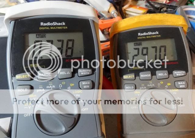
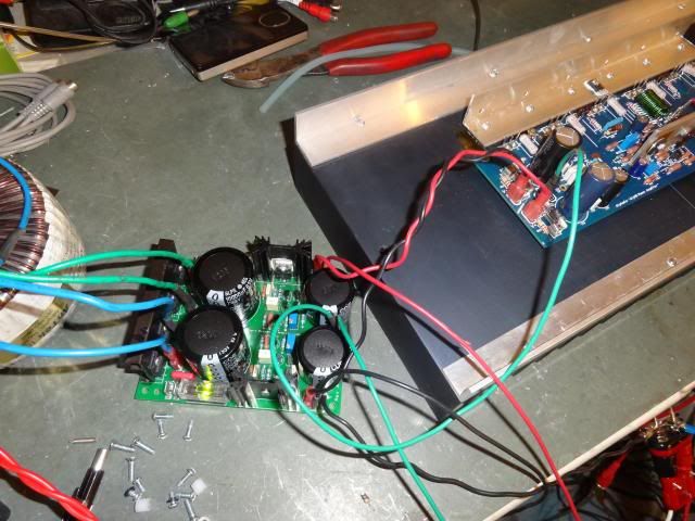
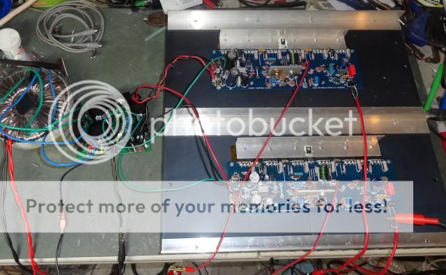
I finished up populating the boards and hooked them up. I had problems with one of them because the built in jumpers at C18 and C19 were no good I had to install wire jumpers to get them to work. They were fine on one board but not the other. Anyway, I got that resolved. I powered them up using a 600VA 25-0-25VAC Antek and a Mr Evil Finished capacitance multiplier. I turned it up a bit with my Variac and am getting +/-47.5V rails. I was able to get the front end set, DC offset is at -00.1mv and I set the bias to 20mv across TP1 & TP2. Everything looks good but when I hook up the scope and sinewave generator with an 8R dummy load, I get what appears to be oscillation at about 29VAC output. I have attached some pics for clarity. Any help will be greatly appreciated.
Thanks, Terry
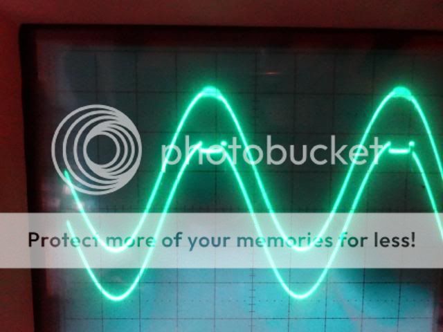
The input is the top trace and the output the lower.

Input voltage on the left and output on the right.
If you look here, you can see that the input, which is on top is picking up the oscillation as well. That is coming from the amp, not the generator.
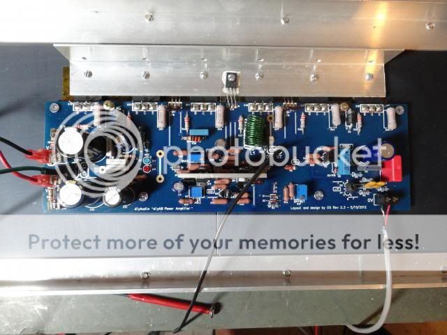
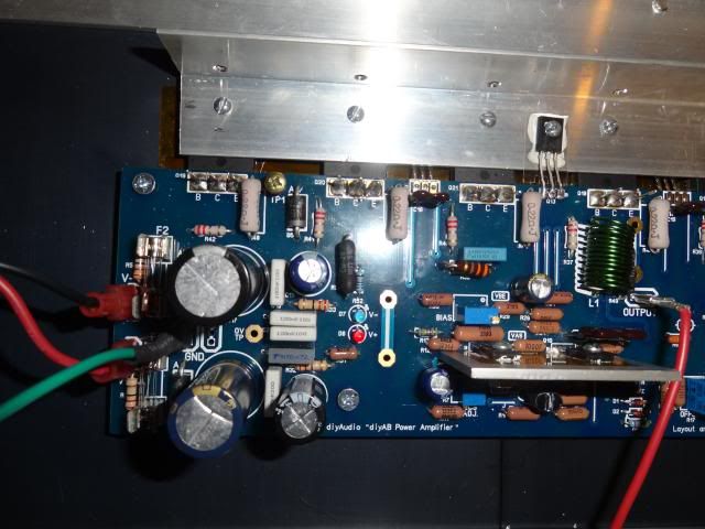
Just a picture of one of the boards, as mounted on the heatsink.
I finished up populating the boards and hooked them up. I had problems with one of them because the built in jumpers at C18 and C19 were no good I had to install wire jumpers to get them to work. They were fine on one board but not the other. Anyway, I got that resolved. I powered them up using a 600VA 25-0-25VAC Antek and a Mr Evil Finished capacitance multiplier. I turned it up a bit with my Variac and am getting +/-47.5V rails. I was able to get the front end set, DC offset is at -00.1mv and I set the bias to 20mv across TP1 & TP2. Everything looks good but when I hook up the scope and sinewave generator with an 8R dummy load, I get what appears to be oscillation at about 29VAC output. I have attached some pics for clarity. Any help will be greatly appreciated.
Thanks, Terry
The input is the top trace and the output the lower.

Input voltage on the left and output on the right.

If you look here, you can see that the input, which is on top is picking up the oscillation as well. That is coming from the amp, not the generator.

Just a picture of one of the boards, as mounted on the heatsink.

Does R50 get warm (hot) ?
Also , your 3rd pix shows the output devices bolted upside down (plastic facing up in contact with the aluminum)?? They should be on top of the aluminum with mica/silicone insulators. Semiconductor metal - insulator - aluminum (with thermal compound).
GROUND the heatsink !!
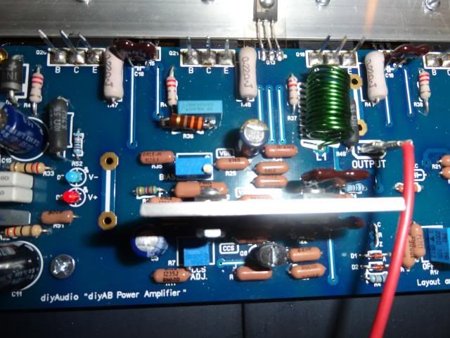
Show a large detailed picture of the board (a couple close-ups).
R14 should have 7-8v across it ... 3.7ma for LTP Q1-2 from the small current source.
R27 = .6V ... that is the 8ma VAS current (the other current source - Q11-12).
This amp's stability (phase margin) is controlled by R15/16 , R20/21, R23 (emitter resistors for Q1-2 , 5-6 , and 10). C7-8 in series is equivalent to about 80pf.
Check to see that the above components are correct.
Unlike some DIY amps , this one has base stoppers on both CCS's ,and the outputs. This was a design consideration to make it much less likely to oscillate.
OS
Also , your 3rd pix shows the output devices bolted upside down (plastic facing up in contact with the aluminum)?? They should be on top of the aluminum with mica/silicone insulators. Semiconductor metal - insulator - aluminum (with thermal compound).
GROUND the heatsink !!
Show a large detailed picture of the board (a couple close-ups).
R14 should have 7-8v across it ... 3.7ma for LTP Q1-2 from the small current source.
R27 = .6V ... that is the 8ma VAS current (the other current source - Q11-12).
This amp's stability (phase margin) is controlled by R15/16 , R20/21, R23 (emitter resistors for Q1-2 , 5-6 , and 10). C7-8 in series is equivalent to about 80pf.
Check to see that the above components are correct.
Unlike some DIY amps , this one has base stoppers on both CCS's ,and the outputs. This was a design consideration to make it much less likely to oscillate.
OS
By Still4given- built in jumpers at C18 and C19 were no good I had to install wire jumpers to get them to work
I just tested my 4 V2.3 boards. All the topside jumpers show continuity.
I might of been premature in your heatsinking method. Is that angle pushing down across the top of all the devices? Still , ground the main heatsink.
As far as C18 and C19 , they are an option if you use fast drivers (toshiba)...
MJE-xx's really do not need them.
The oscillation feeding back to your signal generator through the amp's circuitry seems improbable. More likely it's feeding back through some ground loop.
The oscillation also seems to be occurring when the ksa1381 (Q10) "sticks"(latches up). I've seen this in some simulations but never with an actual amp.
Try reducing R23 to 47R or even 56R to reduce the gain of Q10.
What grade Q10 are you using D,E,or F ??
Using the multipliers also adds another variable (interaction ?) to the "mix" ...
try powering with a "straight" unregulated supply , as this is what this amp is intended for. The amp's built- in CRC supply (C10-17/R32-33)+ it's PSRR is sufficient.
PS - on my earliest amp , my zoble was warm (oscillation) using similar amps in a wooden box with jury-rigged heatsinks. A kind DIYA member suggested that my output device-heatsink setup was just one big parasitic capacitance waiting to happen. He was right ! problem solved ....
OS
Last edited:
Does R50 get warm (hot) ?
No, barely warm
Also , your 3rd pix shows the output devices bolted upside down (plastic facing up in contact with the aluminum)?? They should be on top of the aluminum with mica/silicone insulators. Semiconductor metal - insulator - aluminum (with thermal compound).
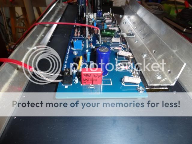
That pic is deceiving. The devices are mounted on the heatsink with kapton tape and compound. the aluminum you see is an angle, bolted to the top of the devices as a washer to spread the clamping pressure and act as a mount for 13 as in the build instructions. See pics below.
GROUND the heatsink !!
Will do. I did hook up a ground wire and there is no change in that oscillation.
Show a large detailed picture of the board (a couple close-ups).
See below
R14 should have 7-8v across it ... 3.7ma for LTP Q1-2 from the small current source.
I have it set at 8.25V per build instructions. Should I lower it?
R27 = .6V ... that is the 8ma VAS current (the other current source - Q11-12).
I measure .523V, is this close enough? If not, How do I adjust?
This amp's stability (phase margin) is controlled by R15/16 , R20/21, R23 (emitter resistors for Q1-2 , 5-6 , and 10). C7-8 in series is equivalent to about 80pf.
Check to see that the above components are correct.
I was very careful to make sure everything is per BOM. I did use MPSA06 for Q1/2 because I had a bunch of them and some good matches.
One more question, What is the purpose of R53 & 54? They are by-passed by the fuses. The reason I asked is because one of the boards blew a fuse and I didn't notice and now I have a big black spot where R54 used to be. How important is it that it is 22R? Will 27R work OK?


No, barely warm
Also , your 3rd pix shows the output devices bolted upside down (plastic facing up in contact with the aluminum)?? They should be on top of the aluminum with mica/silicone insulators. Semiconductor metal - insulator - aluminum (with thermal compound).
That pic is deceiving. The devices are mounted on the heatsink with kapton tape and compound. the aluminum you see is an angle, bolted to the top of the devices as a washer to spread the clamping pressure and act as a mount for 13 as in the build instructions. See pics below.
GROUND the heatsink !!
Will do. I did hook up a ground wire and there is no change in that oscillation.
Show a large detailed picture of the board (a couple close-ups).
See below
R14 should have 7-8v across it ... 3.7ma for LTP Q1-2 from the small current source.
I have it set at 8.25V per build instructions. Should I lower it?
R27 = .6V ... that is the 8ma VAS current (the other current source - Q11-12).
I measure .523V, is this close enough? If not, How do I adjust?
This amp's stability (phase margin) is controlled by R15/16 , R20/21, R23 (emitter resistors for Q1-2 , 5-6 , and 10). C7-8 in series is equivalent to about 80pf.
Check to see that the above components are correct.
I was very careful to make sure everything is per BOM. I did use MPSA06 for Q1/2 because I had a bunch of them and some good matches.
One more question, What is the purpose of R53 & 54? They are by-passed by the fuses. The reason I asked is because one of the boards blew a fuse and I didn't notice and now I have a big black spot where R54 used to be. How important is it that it is 22R? Will 27R work OK?


I nominate Terry to be the beta tester for future boards. He seems to have an uncanny ability to find all available problems.
LOL. I must say, I was pretty surprised when I fired it up and everything looked right. If I hadn't hooked up the generator and scope, I probably wouldn't have known there was a problem. It is right at the point of clipping and I never run an amp that hard. It has been playing music for three hours now and sounds fine. One board still has a potential issue but I won't know until I can replace R54. I seem to be out of 22R 1/2W resistors. I may throw something else in there temporarily since it is bypassed by the fuse anyway.
The oscillation feeding back to your signal generator through the amp's circuitry seems improbable. More likely it's feeding back through some ground loop.
The oscillation also seems to be occurring when the ksa1381 (Q10) "sticks"(latches up). I've seen this in some simulations but never with an actual amp.
Try reducing R23 to 47R or even 56R to reduce the gain of Q10.
What grade Q10 are you using D,E,or F ??
I used MJE350 for Q10
sPS - on my earliest amp , my zoble was warm (oscillation) using similar amps in a wooden box with jury-rigged heatsinks. A kind DIYA member suggested that my output device-heatsink setup was just one big parasitic capacitance waiting to happen. He was right ! problem solved ....
OS
I'm not using a Zobel, should I?
Thanks, Terry
You can use 27R for R53-54. These are there just to make sure you still have both rails in case you do blow a fuse (safety feature).
If you are using a MJE350-pnp , use mje340's for Q11/12. The MJE350 is slower than a ksa1381. Many MJE340/50 parameter's are [unknown} .http://www.fairchildsemi.com/ds/MJ/MJE350.pdf
You have me thinking .... Some other members mentioned that the gain was too high (35X+). Simply lower R3 and R6's value to 22K for a more manageable 25X gain. Better for a 2V+ preamp output and the stability stays the same.
For a decent test , run a square wave (below clipping level) after you do the reduction in gain.
This behavior (Q10 "latchup") was explored .... http://www.diyaudio.com/forums/solid-state/133306-frugalamp-os-9.html#post1687213
... read most of the page , this seems to be a small issue with this topology ("latchup saturation") . Andy C. and others left DIYA and I saw the solution to this issue on his forum .. Andy's Audio and Electronics Design Topics
BUT ... the added complexity for a DIY project was not worth it.
The Zoble will absorb most of this parasitic oscillation that only occurs if you clip this amp hard.
I have actually clipped mine on occasion , but never "hard". No blown tweeters or other drivers. I did blow a woofer right out of it's frame (on purpose) ... the amp survived !
BTW-The zoble is integrated into the board (R50/C21) , so .. no, you don't need one.
Since you are using the MJE350 ,typically Hfe 30-50 (lower gain than a KSA1381) ... leave the 33-47R (R23).
Your 8.25v = 3.75mA - perfect....
Your .523 = 7.7mA for the main current source - perfect for ksa/ksc devices. MJE350/340 perform better with a little more current (9-11ma). Reduce R27 to 56R (11ma). make sure you "unbias" your outputs first , as the higher VAS current will increase the output device current slightly.
OS
Playing in stereo. As said, Antek 5225, Mr Evil,PMI capacitor multiplier, running at +/-37V rails. I'm driving it with my B1 Mezmerize through some JBL 4412 monitors. Sounds pretty sweet. I may stay with the combination. I plays plenty loud and has good sound at normal listening level. I don't really see a need to go up in power. However I could have probably gone with half the heatsink. These are barely warm and I have the bias set at 30mv across TP1 & 2. Letting them burn in for awhile and I'll recheck things.
I replaced R54 with a 1/4W 22R and left the legs long so if it ever goes it won't burn any more of my board.
Blessings, Terry
I replaced R54 with a 1/4W 22R and left the legs long so if it ever goes it won't burn any more of my board.
Blessings, Terry

Good job!
After refining some of the parameter's as I highlighted above - the little 'bugs" will go away.
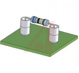
I'm going to use lead spacers (below-"ceramic resistor lead spacer") for my R53/54 just to be safe.
You could go for 60-65V rails and have a concert with those heatsinks -(200W+ peaks )!
OS
After refining some of the parameter's as I highlighted above - the little 'bugs" will go away.
I replaced R54 with a 1/4W 22R and left the legs long so if it ever goes it won't burn any more of my board.
I'm going to use lead spacers (below-"ceramic resistor lead spacer") for my R53/54 just to be safe.
However I could have probably gone with half the heatsink
You could go for 60-65V rails and have a concert with those heatsinks -(200W+ peaks )!
OS
Attachments
- Home
- Amplifiers
- Solid State
- diyAB Amp The "Honey Badger" build thread