


Pete, a quick and dirty DMM check of my MPSA18 (Q1/2) shows Hfe of about 1350. Rather inconveniently, I don't have any more resistors in the 220R range, but should get some delivered in a few days. Failing that I might try swapping to the KSC1845's, which will take a while longer to get here.
I'm using KSC1845F's for Q3/4 and KSA992's for Q5/6 as per your model.
Janusz, I am going to try tracing through the board to see if I can't find anything more useful in terms of pinpointing the problem.
Cheers
I'm using KSC1845F's for Q3/4 and KSA992's for Q5/6 as per your model.
Janusz, I am going to try tracing through the board to see if I can't find anything more useful in terms of pinpointing the problem.
Cheers
Is it an increase of hFE that increases the gain of the stage?
Or is it an increase of gm that increases the gain of the stage?
You can reduce the gm by reducing the Ic of the LTP and/or by increasing the degeneration resistors.
Most use gm/Gm to describe tubes or Jfets , but it can also describe small signal BJT behavior.
the internal physics of a BJT is that it acts as a transconductance amplifier with a low input impedance between base and emitter.
The small-signal transconductance gain value (which varies inversely with emitter current) is typically used when analyzing the small signal characteristics of AC amplifiers.
For ease of calculating large signal, switching, and DC bias calculations, the current gain (Hfe or β) of the transistor is typically used since the BJT externally looks much like a current amplifier for large signals.
Yes , you can (your last statement). That is why I recommended 220R for R14/15. Reducing Ic would also lower the gm of the mirror. The MPSA18 must have a (much)higher gm. Better to use something that "matches" the mirror (Q5-6) .. and run 3-4 mA CCS.
I have used the ss9014 and ksc1845 with no issues , never the mpsa18.
Perhaps I should edit the BOM for ONLY
BC546/7a-b , ksc/2sc1845(f) , ss9014(b-c).
OS
Last edited:
Are you confirming that hFE is not the culprit?
Hfe(current gain) and Gm seem to be proportional.
Googled this :
Electronic Circuits - I - A.P.Godse U.A.Bakshi - Google Books
Most datasheets do not list gm as this is also dependent on the associated
circuit parameters (Vce/Re/Ic/Ibe).
All we have is Hfe
 (unless we have a scope).
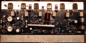
In this instance , the builder used a high gain MPSA18 LTP and encountered oscillation.
I know he used:
ksa992 -current mirror
ksc1845-cascode
12v zener w/ C-Z jumper in.
I don't know his driver/OPS choices. (A full photo would answer all
)No one who used the other LTP choices had this issue
So , I suspect the LTP.
OS
Hi guys,
I'm laying out my Honey Badger to build the case while waiting for the transformer to arrive. Quick question, I'm doing a dual power supply build using the new DIY psu boards, they're pretty wide. For the sake of reducng the foot print I was considering stacking the PSUs on top of each other, with the proper spacers of course. Does anyone think this is a bad idea ? Also so far I am going with one soft start, but since I'm using 2 PSUs with a lot of capacitance should I add another so that each PSU has it's own ?
Thanks for your sage advice in advance.
PJN
Attachments
I used to use MPSA18 in more distant past quite frequently as one could select some with pretty good noise figures. In RIAA or play back head preamps with well regulated quiet PS they performed pretty well. Main problem with MPSA18 is that their parameters vary a lot and in input stages of PAs with non-regulated PS their non-linearity (Hfe changes with Ic) may become a problem.
Apart from ss9014 2sc/ksc1815 may perform well as it is very linear and has decent low noise performance, while their P partners (ss9015 or 2sa/ksa1015) could be used in mirrors.
cheers,
Apart from ss9014 2sc/ksc1815 may perform well as it is very linear and has decent low noise performance, while their P partners (ss9015 or 2sa/ksa1015) could be used in mirrors.
cheers,
Most important for the great sonic character of this amp was to change the imput capacitor "C1". I used in mine a Clarity Cap SA 4.7uf.
Regards
Simon
From what I can find, the Clarity Cap SA 4.7uf only comes in a 630Vdc. Is that what you used?
From what I can find, the Clarity Cap SA 4.7uf only comes in a 630Vdc. Is that what you used?
Yes. That's what I used.
Hi Guys,
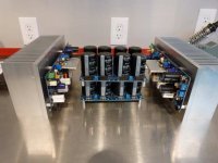
I have a question about the build concerning jumpers. In the build guide the only jumper mentioned specifically is the C to Z jumper for the cascode/current mirror section. However in the pictures and on the board there are many spots for jumpers, there's three next to the home made inductor as an example. In the pictures that show the prototype board in the build guide there are wires shown in the jumper spots. So far the only jumper that I've installed is the C to Z jumper for the zener reference. Do I need to install jumper wires in all of the other spots. Below is a pic of the current state of my build for reference.
Thanks,
PJN
Attachments
cammy,
Have you fixed your Honey Badger? If yes what was the main problem? Only high Hfe of MPSA18s?
In diamond there were many problems, not just one and one of these were some poor quality jfets (possibly fake as it was a chinese kit), some rsistor and capacitor values or lack of these where they should have been.
cheers,
Hi Janusz
Unfortunately, I have not had the time recently to try and fix the problem. All of my parts are from Mouser, so I'm hoping they're good quality. Hopefully I'll get some time and the new parts soon. I'll definitely keep you all updated with my progress, as I really appreciate the advice!
cheers
Unfortunately, I have not had the time recently to try and fix the problem. All of my parts are from Mouser, so I'm hoping they're good quality. Hopefully I'll get some time and the new parts soon. I'll definitely keep you all updated with my progress, as I really appreciate the advice!
cheers
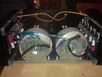
I haven't had much time recently but I did get my transfos mounted and the unused leads tied off. I used mounting brackets from Apex Jr.Home Page.
Does anyone know how to clean off the excess thermal grease that squeezed out? Purely cosmetic, it just looks messy.
Does anyone know how to clean off the excess thermal grease that squeezed out? Purely cosmetic, it just looks messy.
Attachments
Use an oil dampened paper tissue to wipe off the worse excess.
It is the oil in the paste that keeps the air out of the thermal interface. This oil MUST not be washed or dissolved out.
When you get around to cleaning the heatsink of staining and decide to use a solvent dampened paper tissue, DO NOT let any solvent wick under the device or it's mica washer.
It is the oil in the paste that keeps the air out of the thermal interface. This oil MUST not be washed or dissolved out.
When you get around to cleaning the heatsink of staining and decide to use a solvent dampened paper tissue, DO NOT let any solvent wick under the device or it's mica washer.
- Home
- Amplifiers
- Solid State
- diyAB Amp The "Honey Badger" build thread