For best heat transfer you would place the right amplifier board upsidedown.
Regards, Loek
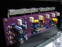
Yes, but I can't do this due to the size of the input caps. This is the only orientation that works with these transfos.
Takin' the plunge ...
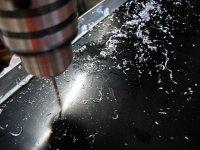
After burning some $$ for speakers (photo 1) , I need some badgers !
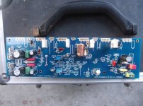
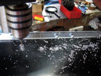
I had the prototype badger (photo 2) , 2 vintage receivers to fill in while I
stuff some PCB's.
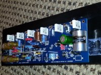
While "stuffin' " , I omitted R53-54 (don't need them) , I might omit C18/19 or
just use some higher voltage 22pf SM caps.
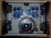
These boards replaced 3 PCB's in my original amp.
I ran into NO errors in hole size with the parts at hand. The PCB's are quite durable ,
no lifting tracks .... I even re-soldered a few things- TOUGH!!
Plated-through holes are a little difficult to rework , have a needle or good a
de-solder braid handy.
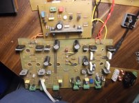
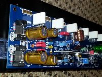
(photo 3) shows the caps, diodes , I even had some real Noble emitter
resistors.
I floated the higher power resistors and 4A diodes above the PCB - if something
did go wrong ... they would emit magic smoke without harming the PCB.
Edit - jumpered the V+ rails as well - can't be too careful.
Wanted to build this for a long time !")
OS
After burning some $$ for speakers (photo 1) , I need some badgers !
I had the prototype badger (photo 2) , 2 vintage receivers to fill in while I
stuff some PCB's.
While "stuffin' " , I omitted R53-54 (don't need them) , I might omit C18/19 or
just use some higher voltage 22pf SM caps.
These boards replaced 3 PCB's in my original amp.
I ran into NO errors in hole size with the parts at hand. The PCB's are quite durable ,
no lifting tracks .... I even re-soldered a few things- TOUGH!!
Plated-through holes are a little difficult to rework , have a needle or good a
de-solder braid handy.
(photo 3) shows the caps, diodes , I even had some real Noble emitter
resistors.
I floated the higher power resistors and 4A diodes above the PCB - if something
did go wrong ... they would emit magic smoke without harming the PCB.
Edit - jumpered the V+ rails as well - can't be too careful.
Wanted to build this for a long time !
OS
Attachments

Last edited:
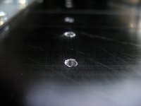
I haven't had much time recently but I did get my transfos mounted and the unused leads tied off. I used mounting brackets from Apex Jr.Home Page.
Does anyone know how to clean off the excess thermal grease that squeezed out? Purely cosmetic, it just looks messy.
I noticed you have your drivers and Vbe on a separate heatsink.
No , NO ...This WILL cause thermal runaway.

Q13 MUST be on the main heatsink !
OS
I noticed you have your drivers and Vbe on a separate heatsink.
No , NO ...This WILL cause thermal runaway.
Q13 MUST be on the main heatsink !
OS
Huh. Glad you have an eagle eye!
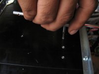
OK, so can someone school me on the best way to tap the heatsink? I'm thinking this tap will work. How does one use it? Drill a slightly smaller diameter hole, then use a wrench to drive the tap in?
VERMONT AMERICAN Hand Tap, Metric, M4-0.70mm, Metric - Taps - 2NWT9|21117 - Grainger Industrial Supply
VERMONT AMERICAN Hand Tap, Metric, M4-0.70mm, Metric - Taps - 2NWT9|21117 - Grainger Industrial Supply
OK, so can someone school me on the best way to tap the heatsink? I'm thinking this tap will work. How does one use it? Drill a slightly smaller diameter hole, then use a wrench to drive the tap in?
VERMONT AMERICAN Hand Tap, Metric, M4-0.70mm, Metric - Taps - 2NWT9|21117 - Grainger Industrial Supply
Drill the proper size hole ensuring the drill bit remains at 90 degrees to the heat sink! I often use cutting fluid when but on an aluminum heat sink I don't because I don't want the petroleum contaminants (cutting fluid) on the matting surface for the power transistors--your choice, but if you do use cutting fluid ensure you clean very well with a cleaner that does not leave a residue. You can find the proper size drill bit on the web. The size of the drill bit changes depending on the pitch and material you intend on taping into. After you look at the proper size drill bit, you may consider changing your thread pitch (I would go with more coarse thread pitch than 0.70). When you start your tap take it slow and turn clock-wise a turn and then back it out until you see the metal shaving clear out. keep repeating the process until you get the depth of thread you desire. Don't push it or you will cross thread the tap!!! You may want to practice on a scrap piece of aluminum to get the idea. I linked an example of many tap size charts available on the net. You may want to compare results as I am not condoning the accuracy of this one. I have one in my tool box with my tap and die set that has never let me down. I hope this helps.
Tap Size Chart
Jason
After you look at the proper size drill bit, you may consider changing your thread pitch (I would go with more coarse thread pitch than 0.70).
Disregard the thread pitch comment, my pitch-o-meter was misaligned...
Just out of curiosity, what are you using 4mm on?
Jason
OK, so can someone school me on the best way to tap the heatsink? I'm thinking this tap will work. How does one use it? Drill a slightly smaller diameter hole, then use a wrench to drive the tap in?
VERMONT AMERICAN Hand Tap, Metric, M4-0.70mm, Metric - Taps - 2NWT9|21117 - Grainger Industrial Supply
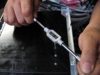
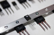
Are you going to tap it to install transistors? You may want to use a size M3 for 3mm bolts.
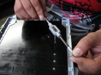
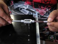
Essentially what you do is drill a smaller hole, use a tapping tool to hold the tap and put some oil/lubricant and just carefully drive the tap in clockwise for a few turns and then go back counter-clockwise. Repeat until you have reached your desired depth.
I hope these photos helps. You can be tapping tens of holes confidently with a little bit of practice.
I would suggest you practice with aluminum, it's kinda gummy so machine oil is a must so you won't foul your tap.
Cheers
EDIT:
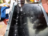
Btw, you can use a 10mm drill bit to de-burr the tapped hole. That also does the job of chamfering the hole which aids for that perfectly flat matting of the transistor's back and the heatsink. Just run it manually through your fingers.
I would suggest you practice with aluminum, it's kinda gummy so machine oil is a must so you won't foul your tap.
Cheers
EDIT:
Btw, you can use a 10mm drill bit to de-burr the tapped hole. That also does the job of chamfering the hole which aids for that perfectly flat matting of the transistor's back and the heatsink. Just run it manually through your fingers.
Attachments
-
 IMG_3255.JPG416.1 KB · Views: 234
 -
 IMG_3254.JPG359.6 KB · Views: 237
 -
 IMG_3251.JPG421.8 KB · Views: 235
 -
 IMG_3248.JPG358.6 KB · Views: 237
 -
 IMG_3245.JPG430.1 KB · Views: 629
 -
 IMG_3244.JPG436.6 KB · Views: 642
 -
 IMG_3235.JPG498.7 KB · Views: 679
 -
 IMG_3229.JPG468.6 KB · Views: 680
 -
 IMG_3228.JPG492.4 KB · Views: 718
I use 4-40 bolts. Way easier to find here in the good ol' USA. Almost exactly the same size. I use wax for ease of drilling and tapping.
Ultralube? Wax Cutting and Drilling Lubricant 2 Oz | eBay
Ultralube? Wax Cutting and Drilling Lubricant 2 Oz | eBay
Wow! Yeah that's a huge help! I have a countersink bit I can use for the chamfer, works great on cherry so it should be fine on aluminum.
That's great, you can use that to chamfer the hole. It really helps to remove those burrs for a very clean hole.
My favorite countersink for aluminum. Never chatters and is self cleaning.
wgsonline: Weldon 82 Deg Pilotless Countersink For Aluminum- Plastic-Wood #10
wgsonline: Weldon 82 Deg Pilotless Countersink For Aluminum- Plastic-Wood #10
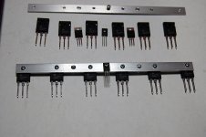
Matt,
This photos may interest you in addressing thermal management of the amp. I used a piece of aluminum to mount the Vbe transistor which is used to also mount and thermally connected to the output transistors. I'm sure you'll get the idea once you see the photos.
Cheers
This photos may interest you in addressing thermal management of the amp. I used a piece of aluminum to mount the Vbe transistor which is used to also mount and thermally connected to the output transistors. I'm sure you'll get the idea once you see the photos.
Cheers
Attachments
I got rubbished for suggesting cooking oil in another Thread.Even cheaper cutting fluid....vegetable oil. Works a treat.
You are right, vegetable oils are very good high pressure lubricants.
Metric taps and drilling size is very easy.OK, so can someone school me on the best way to tap the heatsink? I'm thinking this tap will work. How does one use it? Drill a slightly smaller diameter hole, then use a wrench to drive the tap in?
VERMONT AMERICAN Hand Tap, Metric, M4-0.70mm, Metric - Taps - 2NWT9|21117 - Grainger Industrial Supply
Subtract the pitch from the diameter to give the drilling size.
In aluminium this will give adequate thread engagement (about 90%).
In steel the engagement is too strong (generally) and we use a slightly bigger drilling size to reduce the work the tap has to do and still retain sufficient engagement (about 70%) for the strength required.
don't mount the Vbe tracking transistor to the relatively cool and very slow reacting clamping strip.
Mount it directly on the heatsink next to the hottest device
or
Mount it directly on top of the hottest device
or
Mount a sot23 directly on the Collector (centre lead of a power FET) lead right next to the package.
Mount it directly on the heatsink next to the hottest device
or
Mount it directly on top of the hottest device
or
Mount a sot23 directly on the Collector (centre lead of a power FET) lead right next to the package.
- Home
- Amplifiers
- Solid State
- diyAB Amp The "Honey Badger" build thread