I am not personally afraid... I just don't want it in my home...
What a monster you have made...")
I understand completely.
Not to many audio monsters. I use to work on klystron uhf transmitters. Made 833 look like they ran off a car battery. The b+ was 27 Kvdc.
I've played with 6c21's, 833a's, and 813. But have yet to finish one since I always had to many projects and not enough money, LOL.
Im now trouble shooting a kt88 PP triode amp. Nothing fancy or big and pricey.
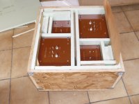
The OPTs and HV chokes are crated and ready to ship from Belgium to New Jersey. See picture.
The crate weighs 92kg!! I'll be picking it up in person at the airport cargo area, guess I need to bring a friend or two.
Still need to finish drilling and then send off the chassis panels for anodizing, so a few more weeks until assembly, but it's getting there.
The crate weighs 92kg!! I'll be picking it up in person at the airport cargo area, guess I need to bring a friend or two.
Still need to finish drilling and then send off the chassis panels for anodizing, so a few more weeks until assembly, but it's getting there.
Attachments
The OPTs and HV chokes are crated and ready to ship from Belgium to New Jersey. See picture.
The crate weighs 92kg!! I'll be picking it up in person at the airport cargo area, guess I need to bring a friend or two.
Still need to finish drilling and then send off the chassis panels for anodizing, so a few more weeks until assembly, but it's getting there.
That is a thing of beauty

"Picture of test amp.....note the "tube socket" made with hose clamps and vice grips! Do not try this at home kids....we are trained professionals. "
im just now getting my brain around tubes. been playing with small tubes with b+ of 300v ish.
my goals are to be half this crazy!
safely..... gose without saying
im just now getting my brain around tubes. been playing with small tubes with b+ of 300v ish.
my goals are to be half this crazy!
safely..... gose without saying
The crate weighs 92kg!! I'll be picking it up in person at the airport cargo area, guess I need to bring a friend or two.
.
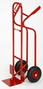
Better way... (no beer needed)

Anyway... congrats & respect!
Attachments
my goals are to be half this crazy!......safely..... gose without saying
For all testing other than that picture there was a 1/4 inch sheet of Lexan between me and the amp, and a fire extinguisher on the floor at my feet! The last thing I wanted was to accidentally have one of the metal guitar strings touch that big power supply while I was holding the guitar.
I'm not crazy, my mother had me tested
My mother had me tested, but the results were "inconclusive" so I was sent to a special school for the 5th and 6th grades.....50 years later the "inconclusive" results were obvious!
My mother had me tested, but the results were "inconclusive" so I was sent to a special school for the 5th and 6th grades.....50 years later the "inconclusive" results were obvious!
LOL. Love you George! Don't ever change.
~Tom
Don't ever change.
I hope not. My wife calls me the 60 year old kid.
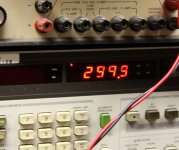
It's been a while due to life's little interruptions, but I am finally back to playing with electricity again. I saw my 8903A hit 299.9 watts a couple of days ago....and this was from a single pair of sweep tubes. As the Mythbusters used to say....It's safe to assume that something's going to go boom!
Attachments
I hope not. My wife calls me the 60 year old kid.
It's been a while due to life's little interruptions, but I am finally back to playing with electricity again. I saw my 8903A hit 299.9 watts a couple of days ago....and this was from a single pair of sweep tubes. As the Mythbusters used to say....It's safe to assume that something's going to go boom!
oh no!
you and myth-busters in the same post!
i better get my fire extinguishers.
i think you should guest host that show.
anyone else think they got a dream job?
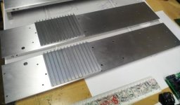
Just a snapshot of the mirror-imaged drilled side panels for the left and right amp. The larger hole is for the RCA jack. I have low profile aluminum heat sinks on each where the Mosfets will attach to the chassis, to help with the heat dissipation (40+ watts from the one in the 833 cathode and another 6 from the one in the gyrator).
I tried to hang as much of the heavy stuff on the extruded aluminum sides as I could in order to reduce somewhat the weight that the top plate has to carry (still a LOT). I still need to do the other sides of each box and once I get the other parts back from FPE, they will go off to Landfall Systems for anodizing.
By the way, if you haven't found Heatsinkusa on the web yet, they are AWESOME! They have a wide variety of aluminum heatsinks, they will cut the lengths and widths exactly to your specs, they ship within a day, and their prices are very reasonable. That's where I got those low profile sinks from.
Extruded Aluminum Heatsinks from HeatSinkUSA
No affiliation, just a happy customer.
Attachments
I was playing around with LTSpice FFT functions today, and found some interesting things regarding the harmonic spectrum in class A1 versus class A2. Thought you all might be interested.
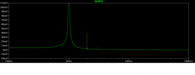
As I've mentioned earlier in this thread, running the B+ at 2300V lets me keep the amp in A1 up to 40W output or so, before any grid current starts flowing in the 833. The first picture below is the distortion spectrum at 38W output into 4 ohms. As you can see, distortion is predominantly second harmonic, with the 2H at .45%. Below this level, the spectrum is consistently 2H dominant.
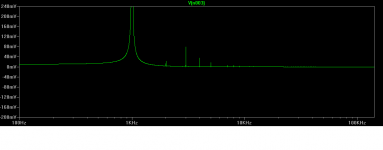
Once the amp goes into A2, however, the distortion spectrum changes, with much less 2H and more 3H. The second picture is the spectrum at 84W output into 4 ohms. Distortion is now predominantly 3H, with the 3H at .76%. This is what was seen in all analyses I ran with the amp in A2.
Anecdotally, I've read reports that A2 sounds a little edgier and a little brighter than A1, and those FFT results seem to reinforce that. In any case, most listening will be in A1, except for crescendos and perhaps drunken volume cranking...
Note: in order to get consistent, believable results from this LTSpice analysis, I had to disable all compression, force double precision math, and set max timestep to 1uS. Otherwise, there's a lot of hash and false peaks along the baseline.
As I've mentioned earlier in this thread, running the B+ at 2300V lets me keep the amp in A1 up to 40W output or so, before any grid current starts flowing in the 833. The first picture below is the distortion spectrum at 38W output into 4 ohms. As you can see, distortion is predominantly second harmonic, with the 2H at .45%. Below this level, the spectrum is consistently 2H dominant.
Once the amp goes into A2, however, the distortion spectrum changes, with much less 2H and more 3H. The second picture is the spectrum at 84W output into 4 ohms. Distortion is now predominantly 3H, with the 3H at .76%. This is what was seen in all analyses I ran with the amp in A2.
Anecdotally, I've read reports that A2 sounds a little edgier and a little brighter than A1, and those FFT results seem to reinforce that. In any case, most listening will be in A1, except for crescendos and perhaps drunken volume cranking...
Note: in order to get consistent, believable results from this LTSpice analysis, I had to disable all compression, force double precision math, and set max timestep to 1uS. Otherwise, there's a lot of hash and false peaks along the baseline.
Attachments
It definitely took longer to simulate with those settings, but the data made a lot more sense. Still it was only a couple minutes total.
Funny how what we think "forever" is keeps changing.
Showing my age, I remember sitting around for hours waiting for FORTRAN programs on a shared mainframe to run in school. Invariably they came back with "error on line..." messages, then it was back to the terminal (sans display screen). Of course, the older guys said I was lucky to have such modern technology...then told me their punchcard horror stories.
Now, I get impatient when my phone doesn't pull up a webpage in 3 seconds or less.
Magz...Remember how long a FFT (written in FORTRAN) took to run on a VAX11/780 around 1980 or so? Same code compiled under Intel FORTRAN runs within a few seconds on a Intel Core processor... Also remember running VMSSpice years ago...making up the run file sometimes took hours...Very interesting transition between A1 and A2 operation on your LTSpice...Haven't played with SE amplifiers much...would be interesting to see the FFT display on a push-pull AB1 type amp at various power levels...
Beware that the simulation is only as good as the models. If your tube model accurately models the tube characteristics and grid current in A2 mode, then you probably get good results. Personally, I've never been able to get accurate prediction of the THD of a tube circuit in LTspice. Especially when the circuit behavior near clipping (or A2) is simulated.
For DC and small-signal AC sims, I generally get a very good match between sims and reality.
~Tom
For DC and small-signal AC sims, I generally get a very good match between sims and reality.
~Tom
- Home
- Amplifiers
- Tubes / Valves
- The Midlife Crisis - My 833C Amp Build