Just to throw this into the mix of confusion...
How does mm7's latest design / theory pair up with the infamous aikido theory? The aikido assumes that a majority of noise will arise from the power supply regardless of how well built the supply is?
So far in our discussions, we assume that our power supplies are just about flat as a reference plate. Mu-Followers tend to handle B+ noise better but what about the different topologies? How worried should we be?
I say this because I ran into this thread while googling about:
Best phono pre-amp tube? - AudioKarma.org Home Audio Stereo Discussion Forums
Some notes?
Attachments
Thanks Ian, I'll try.
I thought that bypassing just removes local NFB improving gain. And as soon as we already have plenty of gain with 3 stages we can sacrifice a little bit gain and also improve sound by removing caps.
Removing cathode bypass caps does not improve sound in most triode topologies. Although there is some small local NFB, there is also a large increase in the effective ra which leads to increased distortion.
Hum should be eliminated by heater elevation. Is it right?
Hum will be improved but un-bypassed cathode resistors in the first stage are a recipe for hum injection. Experience shows that dc heaters are the best option.
6N23P has 20mA max
That's the maximum plate current not the dissipation. 6HN23 plate dissipation is 1.8 watts. With 150V on the plate and 15mA current the dissipation is 2.25 watts.
220uV is after the input transformer. So it will be added by 60dB of tube's amplification, that gives -13dBu. Will it be enough? And again, it is for an ideal weightless ribbon. A real ribbon with mass will produce less voltage.
Oops, my bad. 22uV is about -91dBu. That is a very small input signal by any standards so I agree that as much as 100dB of available gain may be necessary. Note that the best possible S/N ratio is only 40dB.
Yes, and we go back again to PhonoDude! But someone here said that a mu-follower output cascade can work effectively only to one input impedance. that is why I've changed that to White follower, and then to SRPP.
May be it would make sense to change SRPP to White again?
The mu follower is single ended so its drive capability is limited but most will drive +26dBu into a 10K load which is quite sufficient for most uses. The SRPP has an optimum load impedance for maximum output and minimum distortion but it does not vary hugely with load. An SRPP running at the same current as a mu follower will usually do +26dBu into 2K4 as it is a true push pull topology. The White followers only virtyue is its very low output impedance which you don't need. I would stick with an SRPP or a mu follower.
Cheers
Ian
to woodrough.
I do not think that preamp will have sufficient gain.
to Ian,
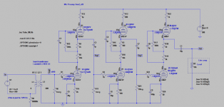
I've found that mu-follower is a best topology from gain and distortion perspective.
The preamp below produces 6V p-p out of input 8.4uV.
The input transformer makes it 84uV, then three MuF cascades based on 12AX7, 6N23P and 6N6P make it to 6.6V with THD 0.004%.
PS. I've modified ribbon mic performance formula so it includes ribbon mass, and mass of air in the gap between magnets/poles where the ribbon is.
For 2"x1/4" ribbon, 1.8 micron thick in 0.4 T field between 1/4"x1/4 baffles gives 0.23uV for 0.02Pa sound pressure (SPL 60dB, speech from 1m distance) and 0.8uV for 0.07Pa (loud singing).
1:37 mic transformer makes it to 8.4uV and 29.9uV accordingly.
then preamp transformer makes it to 84uV and 299uV. With tube noise level ~0.5uV ( http://diyaudioprojects.com/mirror/members.aol.com/sbench102/RAT_Noise/noise4.txt ) it should give 40-45dB S/N.
It is not extremely good, but what can we do? I see only to increase input transformer ratio. How to calculate damping impact on a ribbon if first tube grid resistance will be 1MegO?
I do not think that preamp will have sufficient gain.
to Ian,
I've found that mu-follower is a best topology from gain and distortion perspective.
The preamp below produces 6V p-p out of input 8.4uV.
The input transformer makes it 84uV, then three MuF cascades based on 12AX7, 6N23P and 6N6P make it to 6.6V with THD 0.004%.
PS. I've modified ribbon mic performance formula so it includes ribbon mass, and mass of air in the gap between magnets/poles where the ribbon is.
For 2"x1/4" ribbon, 1.8 micron thick in 0.4 T field between 1/4"x1/4 baffles gives 0.23uV for 0.02Pa sound pressure (SPL 60dB, speech from 1m distance) and 0.8uV for 0.07Pa (loud singing).
1:37 mic transformer makes it to 8.4uV and 29.9uV accordingly.
then preamp transformer makes it to 84uV and 299uV. With tube noise level ~0.5uV ( http://diyaudioprojects.com/mirror/members.aol.com/sbench102/RAT_Noise/noise4.txt ) it should give 40-45dB S/N.
It is not extremely good, but what can we do? I see only to increase input transformer ratio. How to calculate damping impact on a ribbon if first tube grid resistance will be 1MegO?
Attachments
Wait a second. Did I calculated S/N correct?
According to http://diyaudioprojects.com/mirror/members.aol.com/sbench102/RAT_Noise/noise4.txt 12AX7 gives 0.6uV noise in output signal when input signal is 0. Is it correct?
If so, the first stage output signal is ~29mV p-p (for speech input).
Then 29mV/0.6uV gives 95dB S/N ratio. Not that bad!
Am I correct? If yes, we do not need a steeper transformer.
Wait a second. Did I calculated S/N correct?
According to http://diyaudioprojects.com/mirror/members.aol.com/sbench102/RAT_Noise/noise4.txt 12AX7 gives 0.6uV noise in output signal when input signal is 0. Is it correct?
If so, the first stage output signal is ~29mV p-p (for speech input).
Then 29mV/0.6uV gives 95dB S/N ratio. Not that bad!
Am I correct? If yes, we do not need a steeper transformer.
No, those figures are EIN. Thay are also optimistic. They are made on his noise tester which includes an HF filter that improves the figures for tubes where a high ra is used e.g. 12AX7. As I have said several times already, you will be lucky to get an EIN of 2uV for a 12AX7. Typical output noise of a 12AX7 mu follower is 200uVwhich gives a S/N of 43dB.
You also need to work out the microphone/transformer/transformer noise floor. For this you need the ribbon resistance and primary and secondary resistances of the transformer. This will determine the absolute best S/N you can achieve with a noiseless amplifier.
Cheers
Ian
Probably because it is measured it relative to the maximum output level so relative to 0dBu they are 20dB worse.
Cheers
Just to throw this into the mix of confusion...
How does mm7's latest design / theory pair up with the infamous aikido theory? The aikido assumes that a majority of noise will arise from the power supply regardless of how well built the supply is?
So far in our discussions, we assume that our power supplies are just about flat as a reference plate. Mu-Followers tend to handle B+ noise better but what about the different topologies? How worried should we be?
Some notes?
It is quite easy to build an ht power supply with a noise level of around one microvolt.
Cheers
Ian
Probably because it is measured it relative to the maximum output level so relative to 0dBu they are 20dB worse.
Cheers
Also they have a lot less gain, just 40dB ,so the output noise will be proportionally lower. For example, with a 2uV EIN and 40dB gain, the output noise will be 200uV which is -74dBV. Refer that to a nominal 2V rms output voltage and you have an 80dB S/N ratio.
Cheers
Ian
Last edited:
Thanks Ian,
So, the only ways are:
a) increase input transformer ratio - it should be some impact on ribbon, but I do not know how hearable it will be. Read somewhere about tinny sound.
b) improve properties of mic - it is achievable to increase E about 2 times without lowering HF ceiling by using bigger magnets. But 2 times is not too much.
c) find a magic tube with very low Ein noise. Does it exist?
d) base amp on SS.
Thanks Ian,
So, the only ways are:
a) increase input transformer ratio - it should be some impact on ribbon, but I do not know how hearable it will be. Read somewhere about tinny sound.
b) improve properties of mic - it is achievable to increase E about 2 times without lowering HF ceiling by using bigger magnets. But 2 times is not too much.
c) find a magic tube with very low Ein noise. Does it exist?
d) base amp on SS.
Yes, those are your basic choices but bear in mind that even with a completely noisless SS stage you will only improve the S/N by 6dB. You should be able to get 3dB by paraleling two triodes in the very first stage and close to another 3dB by increasing the transformer ratio to 1:14.
I have built several microphone preamps based on a 6CG7 mu follower with nearly 78dB of gain. Output noise is around -47dBu at max gain indicating an EIN of -125dBu and a noise factor of 6dB. When I used a Grampian GR2 ribbon mic with one of these with the gain turned right up the noise is just a gentle background hiss.
The bottom line is your ribbon mic has a noise resistance not a long way from 150 ohms seen at the mic pre transformer input. Its thermal noise is therefore about -131dBu which is about 0.22uV. If your ribbon mic outputs 22uV then you have a 40dB S/N best case, end of story. I would suggest your efforts are best placed in increasing the sensitivity of the ribbon mic.
Cheers
Ian
I also ran into this thread. Pretty juicy read. I think this may be of use. Especially the last few pages
http://www.diyaudio.com/forums/tubes-valves/173443-low-noise-low-microphony-low-hum-valves.html
http://www.diyaudio.com/forums/tubes-valves/173443-low-noise-low-microphony-low-hum-valves.html
I also ran into this thread. Pretty juicy read. I think this may be of use. Especially the last few pages
http://www.diyaudio.com/forums/tubes-valves/173443-low-noise-low-microphony-low-hum-valves.html
The bottom line seems to be that no one has measured better than 1uV EIN for any tube which would just about be sufficient to get below the theoretical noise of a 150 ohm resistor via a 1:10 transformer. The transformer has a NF of at least 1dB so you never quite get there. With a 2uV EIN tube you are only 5dB NF worse off.
Cheers
Ian
Well, it is clear that mic sensitivity should be improved. But unfortunately the easiest way - widening baffles - causes sharp decreasing HF ceiling. With 5mm baffles it is 20KHz, with 7.5mm it is already 14KHz. That is why most ribbon mics sound dark. I do not want to go this way. And another ways are:
a) thinner ribbon. It is already 1.8 microns and mass is 2mg. Making it thinner does not work because it will be impractical (too fragile), and anyway air around it has mass 3mg, that is impossible to remove.
b) increased magnetic field in gap. I am working on a construction but it looks like that more than 2T is not practically achievable because best "flux alloys" have saturation max 2.5T. In my current mic flux is 0.4T.
Meantime I've made another schematic: 1:20 transformer and 2 MuF stages with about 70dB tube gain. THD is 0.001% at speech level.
Attachments
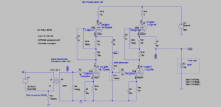
I think you are pretty much on the right track. The 1:20 transformer should get you close to the theoretical noise performance. Just a couple of points. The 12AX7 is low gm so it does not really need a grid stopper. All that 1K does is add some noise you don't want. You should perhaps add a grid stopper to the top tube of the 6N23 mu follower as that is a high mu tube. I would increase the cathode bypass to 220uF on both tubes.
You mentioned you are going to be recording very quiet sounds but you have not mentioned what they are. Is there any opportunity to get the mic closer?
Cheers
Ian
You mentioned you are going to be recording very quiet sounds but you have not mentioned what they are. Is there any opportunity to get the mic closer?
Cheers
Ian
Thanks Ian for good advices.
It was woodrough who was going to be recording very quiet sounds. I just thought it would be nice to have a high gain low noise pre-amp.
I usually recording acoustic guitar and vocal. Voice can go from quiet to quite loud. Getting closer to mic increases proximity effect, which is OK for most cases. So I think I'll stop on this variant and go ahead with soldering it. Unless you would advise 3 stages of low Mu tubes like 6CG7. Or 3 medium/high Mu tubes set to lower amplification mode. What do you think?
I think the two stages you have will be more than enough for most cases. A regular pot is fine for the gain control. The output impedance of the 12AX7 mu follower will be about 1500 ohms so a 100K log pot should be OK.
I agree, enough theory - time to start soldering.
Good Luck
Ian
I agree, enough theory - time to start soldering.
Good Luck
Ian
this has been a great and sturdy learning experience. I think I would like to finally go to the soldering station and try this out. Do you guys insist on an choked power supply? or is a plain old RC supply sufficient (audibly).
Also what is the point of having small resistors at the top of each anode on the mu-followers? 2ohms? is this just for current measuring?
Also what is the point of having small resistors at the top of each anode on the mu-followers? 2ohms? is this just for current measuring?
- Status
- This old topic is closed. If you want to reopen this topic, contact a moderator using the "Report Post" button.
- Home
- Amplifiers
- Tubes / Valves
- Ribbon Microphone Preamp