Big problem
It wont work !
You need dual rails .
send it back to Christi , or just order a new one and keep it for future use .
Cheers
Rens
Small problem, having seen that I ordered L15D and SMPS500RS 48V with single voltage ... any idea if I could run the L15D with this smps (the manul says single voltage
didn`t realize that there are differnet models of the smps500. Now they took a flight to me and I would be glad if I could use them for the L15D.
any idea where to connect GND + and - ?
thanks!
It wont work !
You need dual rails .
send it back to Christi , or just order a new one and keep it for future use .
Cheers
Rens
No
simple answer no , you will be way over the Fets max values .
Cheers ,
Rens
Do you guys know if the L25D can do 2 Ohms safely with +-42v if I change the appropriate resistors to get it to power up at that voltage. If so, will I need to add a fan for cooling?
Thx
Sent from my HTC Amaze 4G using Tapatalk 2
simple answer no , you will be way over the Fets max values .
Cheers ,
Rens
sagami
The "fake" inductor ( if it is , and probably so ) in my L15D is not bad , measuring within 10% of the Sagami specs regarding Rdc and inductance it's not heating up on 50V dual rails and 8 ohm speakers and sounds great . I'll give it a try and order some original ones at RS and hear and measure if it makes any difference .
Cheers ,
Rens
change the mosfets to irfb5615. and change the inductor with an original one from sagami.
The "fake" inductor ( if it is , and probably so ) in my L15D is not bad , measuring within 10% of the Sagami specs regarding Rdc and inductance it's not heating up on 50V dual rails and 8 ohm speakers and sounds great . I'll give it a try and order some original ones at RS and hear and measure if it makes any difference .
Cheers ,
Rens
Gentlemen, please give me a hint how to operate the L15D.
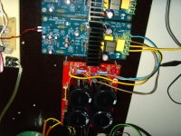
I connected it as shown on the left image as follows:
From bottom to top: +46VDC, Speaker+, GND (GND Speaker), -46VDC.
The input is a 200mV sine wave and should result in a 7V amplitude output sine wave (gain of the L15D is 36).
But the only thing that I see on the speaker's output terminal, is the PWM signal.
What am I doing wrong?
Best regards - Rudi_Ratlos
P.S. Same behaviour on both channels.
Speaker is a 8 Ohm / 100VA resistor.
Attachments
Last edited:
Tekko, I bought from ebay:
L15D Digital Audio amplifier board IRS2092 IRFI4019H | eBay
The kit has been pre-assembled.
Best regards - Rudi_Ratlos
L15D Digital Audio amplifier board IRS2092 IRFI4019H | eBay
The kit has been pre-assembled.
Best regards - Rudi_Ratlos
I have 6 of the bigger brother IRS2092 amp modules to the L15D, the L25D from along on eBay. I purchased them all assembled. I've only had 1 go bad on me. But for $30 I'm not too concerned. I also have 2 other IRS2092 modules from Cristi that are working flawlessly as well. On the first one of Cristi's I pulled a very stupid stunt, and applied about 40% more power than it was designed to handle and while I saw no magic smoke, the protection circuits must have kicked in and worked. Upon receiving a lower powered torodial I powered it back up and it worked fine. Even Cristi was concerned that the original voltage supplied might have been too much and fried something. I think it's just a positive testament to the quality and tolerances of the components he uses.
Rick
Rick
.
But the only thing that I see on the speaker's output terminal, is the PWM signal.
What am I doing wrong?
what is Is the amplitude of the PWM signal ? If you modulate the input, do you see a modulated PWM . Looks like there's something wrong with the output filter , but on both boards ?
Cheers ,
Rens
Rens,
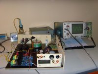
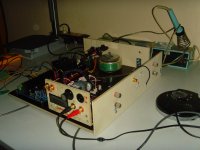
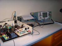
the left image shows my current setup.
CDP connected to passive PreAMP - connected to L15D - connected to a big 8 Ohm resistor as speaker-substitute.
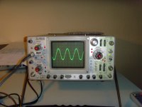
The 2nd picture shows the output with no input applied (Input + = Input -).
The amplitude is about 200mV, the frequency is about 70 KHz.
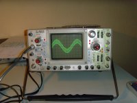
The 3rd picture shows the output with a 100mV / 1 KHz sine wave applied to the input. I call this "heavy oscillation", but I am not sure about class D.
Best regards - Rudi_Ratlos
the left image shows my current setup.
CDP connected to passive PreAMP - connected to L15D - connected to a big 8 Ohm resistor as speaker-substitute.
The 2nd picture shows the output with no input applied (Input + = Input -).
The amplitude is about 200mV, the frequency is about 70 KHz.
The 3rd picture shows the output with a 100mV / 1 KHz sine wave applied to the input. I call this "heavy oscillation", but I am not sure about class D.
Best regards - Rudi_Ratlos
Attachments
Rens,
the left image shows my current setup.
CDP connected to passive PreAMP - connected to L15D - connected to a big 8 Ohm resistor as speaker-substitute.
The 2nd picture shows the output with no input applied (Input + = Input -).
The amplitude is about 200mV, the frequency is about 70 KHz.
The 3rd picture shows the output with a 100mV / 1 KHz sine wave applied to the input. I call this "heavy oscillation", but I am not sure about class D.
Best regards - Rudi_Ratlos
Hi Rudi ,
I don't see any PWM signal on your scope .
To analyse if the problem is in your L15D , disconnect all sources from their power supply and the L15D and short the input of the L15D with a jumper .
Power up ONLY the L15D and measure with a battery powered multimeter on AC to see if you have any signal . It should be near zero Volts. Then try again with some sine wave from an external source and measure .
I see you have a 465 scope , do a differential measurements on channel A and B with 2 probes just using 2 two probe tips and adding the signals , so no earth connected to your L15D through the scope . The scope's GND to the L15D can be the source of the problem.
As you are in Germany you can probably rotate your scope's powerplug 180 degrees and so inverting the power supply . Give it a try .
As the signal is only a couple of hundred millivolts , you can also just check with a speaker , nothing else on the output , no scope . Begin with a shorted input , listen . All OK , than add signal ( from MP3 player or Iphone . etc . )
Then add the scope and see if it starts oscillating .
Cheers ,
Rens
Rens, thank you for your advices.
I rotated the scope's powerplug: no change of the scope's image measuring the output across the 8 Ohm resistor.
I shorted the input: Input + = Input - and measured DC (!) on the output: not measurable.
I read Rod Elliott's article: "Class D Audio Amplifiers - Theory and Design", especially his notes about "Output Filter Design"
and came to the conclusion that my pictures shown may be "true" (Typical Class-D LC 2nd Order Filter).
Then I disconnected the scope, connected a pair of cheap speakers, inserted my favourite CD, powered on and:
there is some beautiful sound coming out of the L15D, no noise or distortion to be heard at all.
Thank you once more for your support - Rudi_Ratlos
Yep, wonderful sounding amps.
The output filter behaviour depends on the load impedance, and as you can see, the residual pwm freq is still there with an 8ohm resistor. (should be around 420kHz).
I measured it pretty strong on my L25D.
Of course it is way above the freq range a tweeter can reproduce. Also, tweeter impedance at 400kHz is far from 8ohm
I built a while a go a simulator with the amp output filter, speaker xover and speaker speaker model supposely accurate at high freq. Results are amazing. Unfortunaterly I never could check against reality due to lack of proper measurement tools.
https://www.circuitlab.com/circuit/h27m67/l25d-27tdc-v2/
The output filter behaviour depends on the load impedance
This is why pre filter feedback selfosch is a BAD design and class d done WRONG!
D
Deleted member 148505
Rens, thank you for your advices.
I rotated the scope's powerplug: no change of the scope's image measuring the output across the 8 Ohm resistor.
I shorted the input: Input + = Input - and measured DC (!) on the output: not measurable.
I read Rod Elliott's article: "Class D Audio Amplifiers - Theory and Design", especially his notes about "Output Filter Design"
and came to the conclusion that my pictures shown may be "true" (Typical Class-D LC 2nd Order Filter).
Then I disconnected the scope, connected a pair of cheap speakers, inserted my favourite CD, powered on and:
there is some beautiful sound coming out of the L15D, no noise or distortion to be heard at all.
Thank you once more for your support - Rudi_Ratlos
Good to hear it's working OK . I was confused by your 70 kHz claim . So the "oscillation" you claimed is just the residue of the carrier frequency around 470 kHz .
Hope you will enjoy this amps as much as I do !!
Cheers ,
Rens
Can I create a good sounding UCD amp just using through hole parts?
I did this with good results but in order to meet EMC requirements, your not getting away from using 100% SMD parts, IR DirectFets included.
TO220 mosfet legs make good antennas at the frequencies that cause EMI issues.
- Home
- Amplifiers
- Class D
- My design L20D IRS2092+IRFI4020H 200W8R