Bob,
In your fig 11.17 on pg 242 you combine "TMC" with MIC. Further, you include a resistor R11 in series with the compensation network.
I am concerned that this resistor may needlessly increase the unity loop gain frequency of the loop enclosing the output stage. This concern derives from the fact that "TMC" appears to introduce an extra zero in that loop over and above the two coincident poles and the zero that are intrinsic to this form of compensation. What do you think?
Bob,
In your fig 11.17 on pg 242 you combine "TMC" with MIC. Further, you include a resistor R11 in series with the compensation network.
I am concerned that this resistor may needlessly increase the unity loop gain frequency of the loop enclosing the output stage. This concern derives from the fact that "TMC" appears to introduce an extra zero in that loop over and above the two coincident poles and the zero that are intrinsic to this form of compensation. What do you think?
Hi Mike,
Good catch. The short answer is that it is my habit to usually place a resistor in series with the compensation network, even a simple Miller one, to add a zero in the open-loop gain to cancel some higher-frequency pole in the output stage that may introduce excess phase. Note that, roughly, the 500 ohms value of the 27pF C1 of the TMC has a corner at about 10MHz, so it is well above the gain crossover frequency. Nevertheless, I agree that caution must always be exercised in applying this trick.
BTW, sometimes such a resistor is added to cancel the RHP zero that exists in Miller compensation due to the finite gm of the VAS. In this case, theoretically, the value of the resistor should be equal to 1/gm of the VAS. This usually means a resistor of quite small value.
I had forgotten that I showed in the book a design that combined TMC with MIC. The other thing in that design of interest was the fact that the TMC network C2 gets its signal from the emitter of the pre-driver, where it has already been buffered from the VAS output node.
Cheers,
Bob
BTW, sometimes such a resistor is added to cancel the RHP zero that exists in Miller compensation due to the finite gm of the VAS. In this case, theoretically, the value of the resistor should be equal to 1/gm of the VAS. This usually means a resistor of quite small value.
As I've pointed out elsewhere, the RHP zero is only an issue if you use a FET TIS which have a much smaller gm than BJTs; a BJT TIS would ensure that the RHP zero is well beyond the unity loop gain frequency and, therefore, need not be compensated for.
I'll try to do a better job in the future writing about TPC and TMC, with more material and better design guidelines.
I suggest every TPC should be bridged. What's more, the bridge should also including output stage. It looks just like Miller Cap in MIC. Thus, you can use larger value for bridge CAP. You will be more confident about the stray capacitance. There is a bunch of benefits if the bridge including output stage. First, less distortion for sure. Second, you can restore 1st order behavior with a well picked cap value. The square wave response will be as clean as the Amp with ordinary Miller Compensation. Third, you can set a higher TPC zero corner frequency without effect global stability.
As I've pointed out elsewhere, the RHP zero is only an issue if you use a FET TIS which have a much smaller gm than BJTs; a BJT TIS would ensure that the RHP zero is well beyond the unity loop gain frequency and, therefore, need not be compensated for.
Hi Mike,
I agree, that RHP is pretty far out in most designs, even when the BJT VAS is typically degenerated to, say 10:1 (RE ~26 ohms when the VAS is operating at 10mA).
Cheers,
Bob
Mr. Cordell, Prof. Cherry in his Electronic World july 1997 article describes (Fig 1d) a topology with Common Emitter OPS and floating power supplies. This has many similarities (?!) with the highly developed Lin topology which is the basis of most PA stuff (ie we can use most of our present pontificating) .. but also many advantages to offset the extra supplies.
John Vanderkooy describes such a beast at A Simple Reliable Power Amplifier with Minimal Component Count
IMHO, this is far more deserving of your attention than even footling differences between 'pure Cherry' and evil TMC
I sincerely hope you will be able to do 'real life' work on this before your next edition.
It reminds me the configuration of the Acoustat Transnova amp :
I suggest every TPC should be bridged. What's more, the bridge should also including output stage. It looks just like Miller Cap in MIC. Thus, you can use larger value for bridge CAP. You will be more confident about the stray capacitance. There is a bunch of benefits if the bridge including output stage. First, less distortion for sure. Second, you can restore 1st order behavior with a well picked cap value. The square wave response will be as clean as the Amp with ordinary Miller Compensation. Third, you can set a higher TPC zero corner frequency without effect global stability.
There is no need whatsoever to bridge the TPC network. Doing so needlessly reduces loop gain without any compensating benefits.
There is no need whatsoever to bridge the TPC network. Doing so needlessly reduces loop gain without any compensating benefits.
It is another story if the bridge including OPS. It won't reduce NFB around the OPS, but it cure the over shoot.
I suggest every TPC should be bridged. What's more, the bridge should also including output stage. It looks just like Miller Cap in MIC. Thus, you can use larger value for bridge CAP. You will be more confident about the stray capacitance. There is a bunch of benefits if the bridge including output stage. First, less distortion for sure. Second, you can restore 1st order behavior with a well picked cap value. The square wave response will be as clean as the Amp with ordinary Miller Compensation. Third, you can set a higher TPC zero corner frequency without effect global stability.
That's a great idea. Thanks. I'll try it.
BTW, although I can't see the big loop gain peak in the closed loop response of conventional TPC, I must admit that I am still uncomfortable seeing it there. A fairly sharp peak in the loop gain in the mid-band just seems undesirable. In high-end audio, things sometimes matter when we can't measure them (or don't measure them because we don't know how, or what to measure).
Cheers,
Bob
....although I can't see the big loop gain peak in the closed loop response of conventional TPC, I must admit that I am still uncomfortable seeing it there. A fairly sharp peak in the loop gain in the mid-band just seems undesirable.
The peak is not that large, and I can assure you it is completely innocuous.
I suggest every TPC should be bridged. What's more, the bridge should also including output stage. It looks just like Miller Cap in MIC. Thus, you can use larger value for bridge CAP. You will be more confident about the stray capacitance. There is a bunch of benefits if the bridge including output stage. First, less distortion for sure. Second, you can restore 1st order behavior with a well picked cap value. The square wave response will be as clean as the Amp with ordinary Miller Compensation. Third, you can set a higher TPC zero corner frequency without effect global stability.
Correct something: The text in Red should be OIC (output stage inclusive miller compensation)
The peak is not that large, and I can assure you it is completely innocuous.
Hi Mike,
As you correctly pointed out, the size of the peak is influenced by whether the VAS has a preceding EF (and probably other things, like whether the output stage is a double or a Triple). In two examples I evaluated, one had a peak of about 20dB near 1kHz and another had a peak of about 10dB near 10kHZ. These are not what I would consider small. As expected, in these designs the sensitivity function for the output stage takes a significant dip at these frequencies.
The figure in my book for the Bridged TPC discussion shows the loop gain for Miller, ordinary TPC and BTPC. The bridging technique does not give up much loop gain to worry about, as far as I can see.
As far as whether the presence of the peak affects sound quality, I don't know. I have not done listening tests between the two. On what basis can you assure us that it doesn't matter? Have you done listening tests to assess this?
Let's bear in mind that we have been discussing small-signal attributes. In a non-linear system, like a real amplifier, I would guess this phenomena would affect the shape of the distortion spectrum, for example, at minimum.
Cheers,
Bob
mid peak in Loop Gain of TPC
Neither in overload performance or recovery even on funny loads. (TPC can be wonky here compared to plain Miller etc but the 'cure' is elsewhere.)
Though I side with Michael in this matter, I'm reminded that what we're arguing over is a single NPO/COG cap") If it doesn't do anything good, it probably doesn't do anything bad either. It's only cos I begrudge every single item in a product.
If it doesn't do anything good, it probably doesn't do anything bad either. It's only cos I begrudge every single item in a product.
To me it sounds like a 'pure Cherry' capacitor to cure the ills of evil TPC
Bob, this is the first evidence I've seen (sim or real life) that the mid peak affects the close loop performance. Can you explain a little more ?... As expected, in these designs the sensitivity function for the output stage takes a significant dip at these frequencies.
Well I have done listening tests on this. In my previous life, I was a Double Blind Listening Test bla bla guru.As far as whether the presence of the peak affects sound quality, I don't know. I have not done listening tests between the two. On what basis can you assure us that it doesn't matter? Have you done listening tests to assess this?
I didn't see ANY change in THD spectrum behaviour over the audio range. But in dem Jurassic times, I couldn't measure THD to better than about 0.003% @ 20kHz.Let's bear in mind that we have been discussing small-signal attributes. In a non-linear system, like a real amplifier, I would guess this phenomena would affect the shape of the distortion spectrum, for example, at minimum.
Neither in overload performance or recovery even on funny loads. (TPC can be wonky here compared to plain Miller etc but the 'cure' is elsewhere.)
Though I side with Michael in this matter, I'm reminded that what we're arguing over is a single NPO/COG cap
If it doesn't do anything good, it probably doesn't do anything bad either. It's only cos I begrudge every single item in a product. Could you post a pic of what you're proposing?jxdking said:I suggest every TPC should be bridged. What's more, the bridge should also including output stage.
To me it sounds like a 'pure Cherry' capacitor to cure the ills of evil TPC
Last edited:
Bob, this is the first evidence I've seen (sim or real life) that the mid peak affects the close loop performance. Can you explain a little more ?
Yes, one way that I evaluate the effect of compensation on distortion performance is to inject a signal into a stage that I am considering for distortion. In essence, I am "making" distortion in that stage. I then look at how that injected signal is attenuated in getting to the output. This is nothing more than a sensitivity test. To no surprise, the sensitivity curve as a function of frequency often looks like the inverse of the loop gain.
Cheers,
Bob
Could you post a pic of what you're proposing?
To me it sounds like a 'pure Cherry' capacitor to cure the ills of evil TPC
Yes, you are right. I proposed bridge Cap for TPC is just like "pure Cherry" capacitor C3.
http://www.diyaudio.com/forums/solid-state/235188-tpc-vs-tmc-vs-pure-cherry.html#post3474671
Can a few people by there simulate a LIN with EF enhanced VAS
and report the VAS buffer input current wafeform with a 1Khz sine
with the amp at about half the max output amplitude.
So far i systematicaly get oscillations with the first cycles although
the VAS output waveform is cleaned thanks to the integration behaviour.
Oscillatory behaviour is compensation dependant , i m still
trying to figure the cause of the whole thing.
Considering e.g. the phase plot in Figure 9.5 on page 179 of your book, I would not be surprised if the versions with and without bridge cap would show different ringing behaviour. Even if a very good input filter is in place, we have to keep in mind that it is impossible in practice to keep high frequency excitations away from the amplifier: distortion residuals, power supply noise, etc. So, if there is a possibility to ring, the circuit will do it.A fairly sharp peak in the loop gain in the mid-band just seems undesirable. In high-end audio, things sometimes matter when we can't measure them (or don't measure them because we don't know how, or what to measure).
Some years ago, I tried to bring an own amplifier to the market. When presenting a certain version of a design to different dealers, I was always astonished how consistent their remarks on strenghts and weaknesses of the sound of this particular version have been. Since that time I recognise that there is virtually nothing that connot be heard.
Best regards,
Matthias
Mr. Cordell, Prof. Cherry in his Electronic World july 1997 article describes (Fig 1d) a topology with Common Emitter OPS and floating power supplies. This has many similarities (?!) with the highly developed Lin topology which is the basis of most PA stuff (ie we can use most of our present pontificating) .. but also many advantages to offset the extra supplies.
John Vanderkooy describes such a beast at A Simple Reliable Power Amplifier with Minimal Component Count
IMHO, this is far more deserving of your attention than even footling differences between 'pure Cherry' and evil TMC
I sincerely hope you will be able to do 'real life' work on this before your next edition.
Hi kgrlee,
Thanks for bringing this to my attention. Is this sort of like the "tail wags the dog" where we have essentially a conventional topology where the conventional output goes to ground and the signal appears on the floating power supply? Something like Crown uses in some of their amps?
I'd like to get a hold of that 1997 EW paper if possible, so I can get a better understanding of it.
It may very well be a topology worth some discussion in the next edition.
Cheers,
Bob
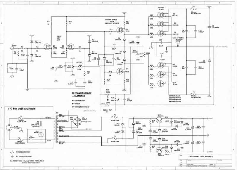
It reminds me the configuration of the Acoustat Transnova amp :
Hi forr,
If I read it right, this Acoustat does look like the "tail wags the dog" topology. Am I right? Thanks for putting this up.
Interesting, looks like they used MOSFETs for the input LTP.
Could you send me an electronic copy of this schematic so that I can see the details more clearly?
Cheers,
Bob
- Home
- Amplifiers
- Solid State
- Bob Cordell's Power amplifier book