That depends.
Thanks for the clarification Klaus
")
Do you think the last layout I've posted can possibly address, at least in part, the (yet to be verified) grounding problem?
If we assume that C14's ripple current will be the main offender, I think this is handled by the new layout.
I'll power the amp from a clean DC lab supply, then inject the ripple current via xformer only hooked up to DR1/DR2, and look what I will get in amounts of ripple at the output. Then use Dremel to cut the slot and check again. Let's hope that the relay current is not a problem, otherwise Q1's emitter needs a different return path as well.
I'll power the amp from a clean DC lab supply, then inject the ripple current via xformer only hooked up to DR1/DR2, and look what I will get in amounts of ripple at the output. Then use Dremel to cut the slot and check again. Let's hope that the relay current is not a problem, otherwise Q1's emitter needs a different return path as well.
If we assume that C14's ripple current will be the main offender, I think this is handled by the new layout.
(...)
Let's hope that the relay current is not a problem, otherwise Q1's emitter needs a different return path as well.
Perfect
Just a thought - since the slight hum changes with touch, could it be related to emissions from the power transformer? These new Antek toroids have what they call a "Magnetic Ring" w/ ground lead to help in eliminating interference. I believe Dario's builds are using R-cores with no shield. Don't know if they even make cans for R-cores.
Just a thought - since the slight hum changes with touch, could it be related to emissions from the power transformer? These new Antek toroids have what they call a "Magnetic Ring" w/ ground lead to help in eliminating interference. I believe Dario's builds are using R-cores with no shield. Don't know if they even make cans for R-cores.
Wouldn't the difference in sound when touched indicate that you are physically transmitting/connecting some part of the circuit to ground?
Is that at all safe?
When you touch a floating heatsink it basically has the same effect as when you touch an isolated but non-shielded piece of wire connected to the amp input. For the same reason, the FE with its rather high 100k input impedance is very prone to capacitive pickup when nothing is connected. The bigger the input cap (C13) the more pickup area you have.
Magnetic pickup is another issue, the thick aluminum base of a heatsink will also partly "absorb" AC fields going through it and therefore fieldlines in its vicinity are bend differently than without it.
Magnetic pickup is another issue, the thick aluminum base of a heatsink will also partly "absorb" AC fields going through it and therefore fieldlines in its vicinity are bend differently than without it.
Just a thought - since the slight hum changes with touch, could it be related to emissions from the power transformer?
I think radiated field from transformers could have a role too.
I believe Dario's builds are using R-cores with no shield. Don't know if they even make cans for R-cores.
My R-Cores are shielded as well and BTW R-Cores are much more silent and radiates less than toroids.
I used anteks steel toroid covers on my 4780 build and it is dead silent with or without source connected. I never operated the amp without them, now I am interested to see if there is a difference. I have been considering the AS-3222 transformer for the FE build over the AN-3222 just for comparison, but either way I will probably use the covers again.
Now im half tempted to take apart my 4780 and do some comparing
Now im half tempted to take apart my 4780 and do some comparing
Another great cap for builders on a budget is the russian polystirene K71-4(film/foil).
Not as good as the Audyns but incredibly good for the price.
They're quite big though, they will not fit perfectly on board.
Very good news about this caps Dario,the seller lives few minutes away from me
and already contacted him.Dario, did you ever tried the LF-01 modules ? The only opinion about these modules are from Bob.
Very good news about this caps Dario,the seller lives few minutes away from me
Good for you!
Dario, did you ever tried the LF-01 modules ? The only opinion about these modules are from Bob.
Sorry, I'm still waiting mines from Siva...
Hummph! http://www.diyaudio.com/forums/anal...screte-hybrid-opamp-module-2.html#post2784782
Note: I believe Siva is two versions beyond the LF01. Awaiting more news.
Note: I believe Siva is two versions beyond the LF01. Awaiting more news.
Last edited:
Dario,
I'm interested in more information about the Russian K71-4 caps. You mentioned that they are bigger than the space on the board. Can tell us the size (body diameter and length) and compare to the True Copper size? Bob's photo of the True Copper caps was instructive.
Also, how would you compare them to BOM Vishay's and the Mundorf ZN, if evaluated?
@atupi,
Did you buy some?
Can tell us the size (body diameter and length) and compare to the True Copper size?
I've not measured them, looking at the auctions they seem 5cm * 3cm.
Also, how would you compare them to BOM Vishay's and the Mundorf ZN, if evaluated?
Between Zn and True Copper.
They're even more neutral than Zns and a bit more refined and tridimensional.
Maybe not as full in the lower bass.
Race ended:
- BMCBob
- SoIL4x4
- Lehmanhill
- b.veneri
- billo44
- arthur
- StefanoSan73
- Suburra
- KSTR
- Randytsuch
- diymax62
- mrsavage
- badrisuper
- pmeade
- TjongKristian
Dario,
I'm interested in more information about the Russian K71-4 caps. You mentioned that they are bigger than the space on the board.
@atupi,
Did you buy some?
Not yet but i will. Already contacted the seller and exchanged telephone numbers.
Hummph! http://www.diyaudio.com/forums/anal...screte-hybrid-opamp-module-2.html#post2784782
Note: I believe Siva is two versions beyond the LF01. Awaiting more news.
I'm about to build some LF-01 from Siva's info to see how they sound. Will keep you informed.
Hi Dario,
Test board (thx again) up and running. Powered from DC lab supply. Input shorted (jumper accross R13).
Good news : Influence of C14 on hum is neglegible so far (I used single diode rectification to increase effect). But the cut doesn't hurt either.
Sensitivity to magnetic fields is also quite low, tape demagnetizer quick test didn't lead to catastrophic results.
Not so good news (in terms of 100% hum optimization) :
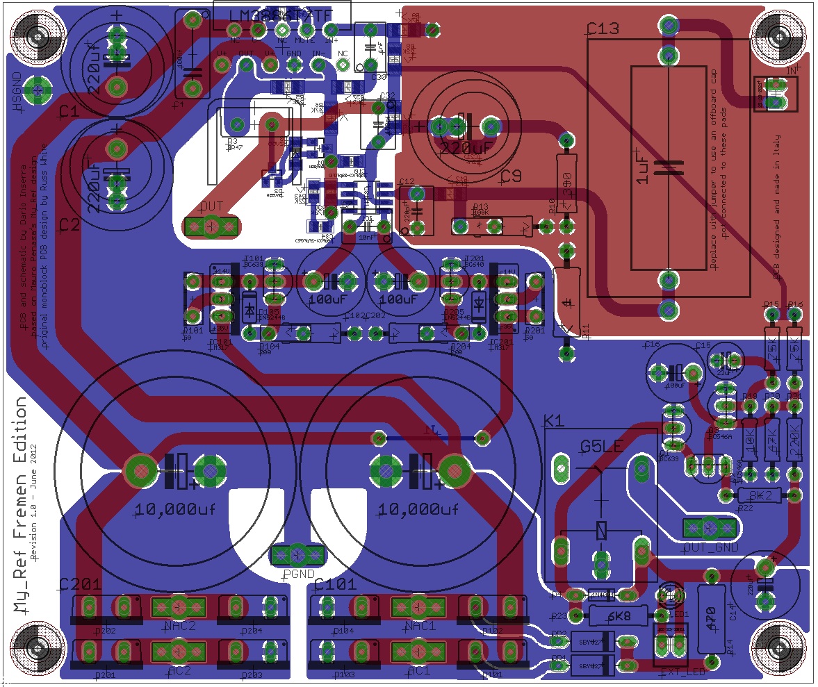
1) C9 is quite good an electrostatic antenna ==> exchange positions of R10 and C9 and minimize trace length on LM318 -IN (Pin3).
2) R11 might better be stuffed as 0R, any current through it causes an input signal.
Both was pretty much anticipated.
And for layout : move R3 a bit so that screwing down the LM3386 on heatsink is made easier.
Circuit issues : Depending on actual power supply (xformer) used, the voltage at the relay drops quite low, 18V or less. Still enough to make it close but a bit sketchy, IHMO. Spec sheet min. is 18V.
More tomorrow evening,
Klaus
Test board (thx again) up and running. Powered from DC lab supply. Input shorted (jumper accross R13).
Good news : Influence of C14 on hum is neglegible so far (I used single diode rectification to increase effect). But the cut doesn't hurt either.
Sensitivity to magnetic fields is also quite low, tape demagnetizer quick test didn't lead to catastrophic results.
Not so good news (in terms of 100% hum optimization) :
1) C9 is quite good an electrostatic antenna ==> exchange positions of R10 and C9 and minimize trace length on LM318 -IN (Pin3).
2) R11 might better be stuffed as 0R, any current through it causes an input signal.
Both was pretty much anticipated.
And for layout : move R3 a bit so that screwing down the LM3386 on heatsink is made easier.
Circuit issues : Depending on actual power supply (xformer) used, the voltage at the relay drops quite low, 18V or less. Still enough to make it close but a bit sketchy, IHMO. Spec sheet min. is 18V.
More tomorrow evening,
Klaus
Test board (thx again) up and running. Powered from DC lab supply. Input shorted (jumper accross R13).
Fantastic!
You're welcome and thank you for doing these tests.
Good news : Influence of C14 on hum is neglegible so far (I used single diode rectification to increase effect). But the cut doesn't hurt either.
Very good news
Sensitivity to magnetic fields is also quite low, tape demagnetizer quick test didn't lead to catastrophic results.

Not so good news (in terms of 100% hum optimization) :
1) C9 is quite good an electrostatic antenna ==> exchange positions of R10 and C9 and minimize trace length on LM318 -IN (Pin3).
Can you elaborate a bit?
What you mean exactly by 'exchange positions of R10 and C9'?
I can't see how...
Minimize trace lenght on -IN... you mean between -IN and C12 or the entire trace?
2) R11 might better be stuffed as 0R, any current through it causes an input signal.
Well, I imagine that it can be shorted with a piece of wire if needed but I would leave the position to be compliant with Mauro's design.
And for layout : move R3 a bit so that screwing down the LM3386 on heatsink is made easier.
Doing this would lengthen the feedback loop, do you think it's mandatory?
Circuit issues : Depending on actual power supply (xformer) used, the voltage at the relay drops quite low, 18V or less. Still enough to make it close but a bit sketchy, IHMO. Spec sheet min. is 18V.
How would you fix it?
Can't be due to the use of a single diode rectifier?
More tomorrow evening,
Can't wait
In the meanwhile I'll play a bit with PCB trying to follow your suggestions...
Thanks for all!
Last edited:
Doing this would lengthen the feedback loop, do you think it's mandatory?
Feedback loop local trace (red) increase by about 30%..
Any opinion?
Attachments
- Status
- This old topic is closed. If you want to reopen this topic, contact a moderator using the "Report Post" button.
- Home
- Amplifiers
- Chip Amps
- My_Ref Fremen Edition - Beta build/Fine tuning