Just to be sure, the acoustic phase you're looking at is place holder data and is invalid. OP was intending to find this out using pink noise/listening tests.The polarity of the mid is wrong, it must be inverted
Your upper point may work.I calculate 500Hz/4000Hz
When I suggested 2800 it was for two reasons. Firstly, cone breakup is just beginning there, and secondly it is becoming directional. Tweeter fs is 700Hz.
Hum, I never calculate any crossover in this thread !
The second order crossover is Istoc's original values. I have just proposed to ajust the levels of the mid-treble.
I made a comment on the crossover of this website : 3-Way Crossover Designer / Calculator
The first order calculator of the three way has a serious problem of polarity on the mid.
I don't need any measurement to prove that : +90 phase shift on the woofer and -90° on the mid... 180° of difference.
So Allen what you're saying is possibly go back through and realign the components closer to E12 standards 10 12 15 etc etc. and get the curves as close as I can within those standards? How might I gain a greater degree of accuracy, I want this to be my best run at building these bad boys I've invested a lot of time thus far and I'm not afraid to invest and learn more. Can you explain your first phrase "A decibel either way is normally OK at this stage of the game, and without impedance phase information the margin of error increases. Furthermore, pay greater attention to the more loud portions (the passband)." a little more to make it a touch clearer, I get the general idea just not fully understanding whats being said.
You've asked a number of question here so I'll make general comments to cover them.
So that it's clear, the series works so that if it mentions 68, for example, you can get 6.8, 0.68, 680 etc... If you want an example of sticking to the values and getting reasonable accuracy, go back to the swd file I posted earlier this week.
You can often fudge them into line with the E series values by changing multiple values to keep in a certain balance. I won't pretend this doesn't require an understanding of what's going on. It's important to mention though that if you feel some value should be different, then do it. You can make it up with multiples of other values (just ask).
I also suggested you pay attention to the more loud portions. This means that if you find diring your tweaking that you have to compromise between getting the top parts of the curve smooth, and the roll-off 'tail' to conform, then the tail becomes the lesser priority. If it helps, once the sound becomes below 24dB less than the main level, you can virtually ignore it. In fact, in engineering terms, 10dB is becoming enough to put it in a lessor category.
How do you get a greater degree of accuracy? I could walk you through taking an impedance measurement with phase. You could also endeavour to get acoustic phase information. Even simpler though, and helpful regardless would be to get yourself a measurement microphone and learn to take plots of your response. This can kind of sidestep your other issues. The incremental information (measurements of the SW crossover in action) can also be fed back into SW to increase your accuracy.
I would advise you that if you're serious about this, you may end up with a pile of discarded components, and it may take quite some time. There are issues that haven't even been discussed yet. Don't worry though, you'll have something that sounds reasonably good soon enough. This is one of the reasons that I suggested that you not obsess over a dB or so at this stage.
If you do get yourself a mic, it should be one with a response that is known and reasonably flat. When you have this, one of the first things you'll want do after first verifying that it all works as expected, is to verify the effects of your baffle. You'll also be able to check the performance of your old system.
.... How might I gain a greater degree of accuracy, I want this to be my best run at building these bad boys I've invested a lot of time thus far and I'm not afraid to invest and learn more...
Invest in a measurement system !
1. A calibrated microphone + stand
Cross·Spectrum Labs - Sound | Vibration | Engineering
I use a soundlevelmeter B&K2231, not ideal but very precise.
2. A jig
http://www.fesb.hr/~mateljan/arta/AppNotes/AP1_MeasuringBox-Rev4Eng.pdf
http://www.google.com/url?sa=t&rct=...sg=AFQjCNHnxnoc65LV85i-DiLgbH9tPvakpA&cad=rja
I made my own jig with amp+souncard in the box and one button to select the type of measurement (calibration, impedance and SPL)
")
3. A soundcard with line input
4. A software...
I use ARTA
Useful links
Gainphile: Cheap and accurate speaker measurement
ARTA Home
Mesure d'impédance et de paramètres T/S grâce à son PC
Measuring Frequency Response Using ARTA
A Speaker Workshop Tutorial
it crashes if you have 2 drivers with the same name.
Thank You!!! Problem solved!
I hate to only be asking questions, it seems as though I'm incompetent. But was the design you outlined when you posted according to my readings accurate enough to actually be used? Because I've always approximated my values and then searched manufacturers to find the parts at or close to the values I had outlined in my plans. It may seem irrelevant but I feel as though if I were to modify your designs I will make my own head spin. Like I did when I adjusted the values to get as close to the reference line as I could without understanding the underlying reason that the values might not work, because not often are they manufactured in every value they conform to the E series values.
It is probably as accurate as I'd care to suggest with the current level of knowledge of the design and evidence to support it. ie: a starting point. I still have reservations about driver blending (power response), baffle effects, and voicing (getting the tone right for you). These will be compounded by phasing issues and room placement concerns.
It's not unusual that I would be stripping out parts for months, and sometimes years with a particular design. That's not to say that I'm never happy...there are varying degrees of happiness, and the changes become very subtle indeed.
For what it's worth, there is no real need to spend big on parts. Electrolytic capacitors and cheap inductors will do. Handfuls of 5W sand cast resistors can be had reasonably.
Hehe, yes that general concern about lifespan is a little overrated. I think it's kind of a hangover from the 1930's, if I remember correctly (no, I'm younger than that ) and the way they couldn't hermetically seal the devices or create durable electrolyte formulas, or something like that.
Colouration can be an issue but it isn't so bad that you can't determine the general suitablility of a component or its value. In fact the influence depends on certain factors and I use electrolytics in some parts of my own finished crossovers without concern.
) and the way they couldn't hermetically seal the devices or create durable electrolyte formulas, or something like that.Colouration can be an issue but it isn't so bad that you can't determine the general suitablility of a component or its value. In fact the influence depends on certain factors and I use electrolytics in some parts of my own finished crossovers without concern.
When tinkering with a sim, I find I like to keep this page open:
Jantzen at parts-express
As well as this page:
Non-Inductive Resistor Index at Parts Express
Then you can sim based on actual available component values (before you have memorized them ). Make adjustments to other components as necessary to compensate but always try to use available values. I have yet to run into a simulation (only being tinkering a few days) where I couldn't come up with a nice flat response using all single components.
Jantzen at parts-express
As well as this page:
Non-Inductive Resistor Index at Parts Express
Then you can sim based on actual available component values (before you have memorized them
). Make adjustments to other components as necessary to compensate but always try to use available values. I have yet to run into a simulation (only being tinkering a few days) where I couldn't come up with a nice flat response using all single components.I'm going to be ordering my crossover components here soon. Thanks Allen for all your help, I modified the curves a touch more with the values available from ERSE's site to get them as close as I possibly could, as you said the information is only so accurate without reading however I'm thinking with your expertise and patience this will turn out fantastically.
Do you think I could make my own PCB to mount these to with 1/4" board and drill the holes necessary to tie down the parts, something cheap like Ply or some other light easy material. Or would it create interference issues?
Seriously though Allen I couldn't have understood half of what I now do without your help. If I ever build another speaker I'll be much more well equipped. I may even buy a Mic
Could we see the final schematic ?I'm going to be ordering my crossover components here soon.
Buy one or build a cheap oneI may even buy a Mic
You can add a mic in your order.
Allen have done a fantastic help assistance
It would just be easier to re-upload the SW files again. I never built them into one solid crossover array in SW because they will be 3 separated crossovers in actuality anyway. The changes were minor at best.
Not big changes I actually left the tweeter completely alone just a nudge here and there.
Not big changes I actually left the tweeter completely alone just a nudge here and there.Attachments
Thanks for the support
Your idea of a board sounds good. Wood is not a bad choice. A final layout should position the inductors so they won't interact with each other or with metal parts.
Could I encourage you to go through at least one round of revisions? Although your layout might not change so your board might still be correct. Anyway, I'd expect at least that you'll want to adjust the bass and/or treble to balance each other. The mic wouldn't go astray.
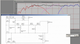
Istoc, I looked the crossover, 87dB, 650Hz-2800Hz... SPL curve is good but:
Sorry , it is not already finished. You have an impedance issue : 2.4 ohms at 700Hz. I verified with actual measurements it was worst. The impedance curve is not very good. You still need crossover work.
1.5 ohms for L1, the 3.3mH is too much ! Keep it below 0.5ohms.
See the schematic below.
Sorry
, it is not already finished. You have an impedance issue : 2.4 ohms at 700Hz. I verified with actual measurements it was worst. The impedance curve is not very good. You still need crossover work.1.5 ohms for L1, the 3.3mH is too much ! Keep it below 0.5ohms.
See the schematic below.
Attachments
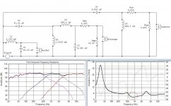
With regard to the impedance dip. Such a dip wouldn't normally put me off, still it should be noted that the impedance file contains invalid phase data and so cannot be trusted.
considering that the L-pad swamps the driver and the first filter has a hand in the potential dip, I've offered a replacement midrange section.
considering that the L-pad swamps the driver and the first filter has a hand in the potential dip, I've offered a replacement midrange section.
Attachments
- Status
- This old topic is closed. If you want to reopen this topic, contact a moderator using the "Report Post" button.
- Home
- Loudspeakers
- Multi-Way
- 3-Way Crossover Assistance Request.