I still hate that coupling capacitor. Hopefully I'll find a way to eliminate it after I get my RevC up running.
It's as easy as jumpering the coupling cap's pads...
")
I think I'm on the right path with new LM318 PS.
Today I've tried the attached simplified version on breadboard and it's a nice improvement Vs the zener shunt.
Bass is tighter, soundstage wider and deeper.
The nice thing is that this simplified version can be easily retrofitted on existing RevC boards.
Stay tuned...
Today I've tried the attached simplified version on breadboard and it's a nice improvement Vs the zener shunt.
Bass is tighter, soundstage wider and deeper.
The nice thing is that this simplified version can be easily retrofitted on existing RevC boards.
Stay tuned...
Attachments

Last edited:
Further development in LM318's PS
Hi all,
I've added a LM317/337 constant current source/sink to the PS, now I'm feeling near to completion.
How it sounds?
Simply great
The schematic of the new PS can be found in the attached updated schematic and PCB layout.
Hi all,
I've added a LM317/337 constant current source/sink to the PS, now I'm feeling near to completion.
How it sounds?
Simply great
The schematic of the new PS can be found in the attached updated schematic and PCB layout.
Attachments


I think I prefer the simplicity of your zener + BC640 shunt regulator alone - with minor modifications, it can be used with NPNs (say BD139 or 2SD667/669) instead of the PNP BC640.
They sound both very very good but the CCS give an extra level of precision. It would be nice to have a discrete CCS though... LM317/337 are not the best CCSs, at least so I've been told.
What is the advantage of using NPNs?
In my mind it should be with BC639/BC640 couple but I've managed to have help only in this way...
Any help, suggestion, fix is as always welcome and appreciated
I've some doubts on the 100uF elcos, probably they're not needed if not detrimental...
Last edited:
What is the advantage of using NPNs?
...
I've some doubts on the 100uF elcos, probably they're not needed if not detrimental...
There's a bit more choice in NPNs - fast, hi-beta, medium-power, etc., and they tend to be slightly less expensive.
How about trying out MKS2XL instead of the Elcos? I only have 2.2uF/50V/5mm, though. Perhaps 10uF MKS2XL (which you perhaps tried out some months ago for C6, C11 in the Rev C?) may be better.
There's a bit more choice in NPNs - fast, hi-beta, medium-power, etc., and they tend to be slightly less expensive.
It could be an option, can you help me adapting the circuit?
How about trying out MKS2XL instead of the Elcos? I only have 2.2uF/50V/5mm, though. Perhaps 10uF MKS2XL (which you perhaps tried out some months ago for C6, C11 in the Rev C?) may be better.
I've those MKS2XL so no problem trying them but, after reading the power supply section here:
L C Audio Technology / ZAPfilter 2
I've the doubt it could work even better without caps.
Another circuit I would like to be able to adapt is this one:
(from TubeCAD)
Last edited:
It could be an option, can you help me adapting the circuit?
I'm trying to help me by myself...
The attached circuit could work?
In this way also the PCB look nicer...
If so the upper part could be used also for the negative side.
What about swapping LM317s with LT1086s?
Attachments


Last edited:
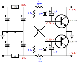
I think I'm on the right path with new LM318 PS.
Today I've tried the attached simplified version on breadboard and it's a nice improvement Vs the zener shunt.
Bass is tighter, soundstage wider and deeper.
The nice thing is that this simplified version can be easily retrofitted on existing RevC boards.
Stay tuned...
Hey Clave,
Am I suppose to be able to work out the retrofitting from your circuit diagram alone? if so I'm gonna need some help....
If the power trace and the power ground are on opposite sides of the PCB, you could make the power trace wide to form some capacitance between it and the ground plane.I'm trying to help me by myself...
The attached circuit could work?
In this way also the PCB look nicer...
If so the upper part could be used also for the negative side.
What about swapping LM317s with LT1086s?
Am I suppose to be able to work out the retrofitting from your circuit diagram alone? if so I'm gonna need some help....
I would say yes...but do thing with care or you can destroy the LM318...
See the attachments.
If the power trace and the power ground are on opposite sides of the PCB, you could make the power trace wide to form some capacitance between it and the ground plane.
Yes, they are.
Do you think that added capacitance could help? Can you elaborate?
How much do you think those traces should grow? They're already 50 mils wide.
Attachments


Last edited:
I'm trying to help me by myself...
The attached circuit could work?
It works...
No apparent change in sound quality.
The fact that this is reduction in inductance with increase in capacitance, it should be much more linear than what you can get out of normal capacitors. I would say as wide as possible without them getting to close to normal signal lines. Theoretically, there should be improvement in detail due to this lower impedance high bandwidth of power supply from this capacitance. I have not directly compared, and it also takes quality (not price) speakers to hear the improvement....
Do you think that added capacitance could help? Can you elaborate?
How much do you think those traces should grow? They're already 50 mils wide.
Generally, I would try to avoid power or ground planes from overlapping with any signal related component or trace. This is because in practice, the ground is not what we theoretically perceive it to be, but just reference for convenience of analysis, calculation, and measurement. Current still flows through it, and the magnetic field will effect the. However, if the ground plane is arranged so that the current paths will be in a wide range of directions, then it probably would not matter so much. It really takes a long time to evaluate an optimum board layout.
The fact that this is reduction in inductance with increase in capacitance, it should be much more linear than what you can get out of normal capacitors.
...
Theoretically, there should be improvement in detail due to this lower impedance high bandwidth of power supply from this capacitance.
It's for this reason that I've made thick power traces on groundplane for the LM3886 PS
Probably the effect, since traces are so short (less than an inch I would say), it's not so important on the LM318 PS.
For instance growing traces from 50 to 70 mils equals going from 1.7 to 2 pF, I think it's not significant...
And traces bigger than 70 mils are not pratical in the space available for the LM318 PS
Generally, I would try to avoid power or ground planes from overlapping with any signal related component or trace. This is because in practice, the ground is not what we theoretically perceive it to be, but just reference for convenience of analysis, calculation, and measurement.
It's so, the plane over the signal portion of the PCB is referenced to 0V zone, which is insulated from the GND by the 1 Ohm resistor.
However, if the ground plane is arranged so that the current paths will be in a wide range of directions, then it probably would not matter so much.
There are multiple ground planes arranged in a (quasi) star-ground so some current returns are constrained.
In addition the 0V ground is insulated from the main ground
It really takes a long time to evaluate an optimum board layout.
I'm trying to do that, since three months ago...
Have you tried calculating the cross section of the LM3886 output pin to where the speaker leads are connected to the PCB? Gradual expansion from the LM3886 output pin cross section to meet the OUT through-hole cross section might be a good idea. This is a small issue, and is debateable whether a difference will be heard or not, but it does not really cost anything, and is a good engineering practice to minimize abrupt change in conductor cross section.
Have you tried calculating the cross section of the LM3886 output pin to where the speaker leads are connected to the PCB?
...This is a small issue, and is debateable whether a difference will be heard or not, but it does not really cost anything, and is a good engineering practice to minimize abrupt change in conductor cross section.
I'll check
I'll check
If I've done the right calculation with 0.35um copper tickness the trace should be 11mm wide (ca 250 mils).
I think it's quite impossible to comply...
I've re-rooted all ground planes and ground connections so to be more compliant with the star ground topology.
Also the 0V top plane has been redisegned so to cover only the input area and where components shunt to ground.
A 0V bottom plane covering the entire amp area has been added and bonded with vias to the top 0V plane so to create a 0V barrier between traces reducing, hopefully, cross-talk.
I think it's needed since I've re-routed the trace to the DC protection circuit to avoid the previous large loop that possibly could have radiated a lot of EMI.
Also main PS traces has been changed to fixed width to mantain impedance constant since they're refererring to a ground plane.
LM318 PS traces has been linked diretly to main smoothing capacitors so to be less influenced by LM3886 back-EMF.
Attachments

10mm square FR4 PCB 1.5mm board thickness = 2.48pF approx.
Track 10mm wide x 100mm long = 24.8pF with ground plane.
It may be worth looking at this to get an idea where return currents flow, dc follow path of leat resistance as the frequency get higher the return currents will flow (or want to flow) under the signal trace, path of least inductance, especialy important for rf frequecies (ie noise) but also for audio frequencys as they span the area where the return current path is moving from resistance to inductance.
http://www.x2y.com/filters/TechDay0...log_Designs_Demand_GoodPCBLayouts _JohnWu.pdf
I interpret that as the problem for those not versed in Ground Plane Design.10mm square FR4 PCB 1.5mm board thickness = 2.48pF approx.
Track 10mm wide x 100mm long = 24.8pF with ground plane.
Unintended parasitics !!
- Status
- This old topic is closed. If you want to reopen this topic, contact a moderator using the "Report Post" button.
- Home
- Amplifiers
- Chip Amps
- My_Ref Fremen Edition - need help on PCB evaluation