C9 is an electrolytic capacitor, if there is a DC offset across this cap then it's fine. If not, then I was thinking about changing it to an bipolar type electrolytic and add a bypass cap to improve it's linearity. I probably should also try it one one of my chip amps too.
a small dc offset is probable, since LM318 is a bipolar opamp, a bipolar caps works as well, in fact there is people that use a bipolar for C9.
Bipolar caps are bigger though (but the 16mm diameter helps...
") ).
).If C13 is moved off board, then you don't really need an AC and a DC input pad. With a coupling cap, it's AC. Without, it's DC. Correct? Although two pads would allow connection of both inputs at the same time (with two input jacks) and not take up much space, and let the builder decide. Kind of a cool idea. Perhaps just label both pads DC+ input. Then the jacks (sockets?) on the chassis would be labeled AC and DC. Is that what you mean, Andrew?
I can't think of a cap that's equal to the quality of this amp that will fit onto the space provided, so it's just as well to leave it off. Using a hefty film cap to connect input jack to board is exactly what should be done. I don't know what else that space can be used for, but it would allow relaxation of the somewhat tight spacing of other components that exists now.
Perhaps install a mounting hole on that side of the board so builders can physically attach the coupling cap against edge of the board instead of it floating around inside the chassis. I attach mine to the chassis floor with a cable tie, but then I must cut it or detach the cap in order to lift the board.
Just throwing out crazy ideas here.
Peace,
Tom E
thanks Dario for starting this thread..for me , your design very nice
Thanks
Using a hefty film cap to connect input jack to board is exactly what should be done. I don't know what else that space can be used for, but it would allow relaxation of the somewhat tight spacing of other components that exists now.
At the moment for nothing...
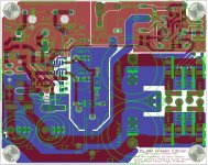
And, probably, the input trace crossing R10 is not a problem at all since since between the trace and the resistor there is the ground plane, which should shield...
And that zone is probably the less congested of all the PCB...
Sincerely, I don't think this or the C13 outboard/onboard are high priority problems, first we shoud:
- find any fault of the PCB layout (if possible)
- design the PS for LM318 (here I need help, I'm not good with transistors)
Perhaps install a mounting hole on that side of the board so builders can physically attach the coupling cap against edge of the board instead of it floating around inside the chassis.
This is a great idea!
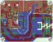
Take a look at the attachment, it could be good?
I've also moved a bit the input connector (it was too near to the edge) and used Russ' C13 so the input is a bit farther from the output ground.
Just throwing out crazy ideas here.
It's called brain-storming...
It works, usually.
Has anyone tried snubbers on the power supply of this amp?
Sorry, this is a taboo...also in the original thread they were proposed upsetting Mauro...
BTW who tried them gave different opinions, some heard an improvement, others didn't.
Rudi, which realized an alternate PCB called X-Calibre, initially tried them and heard an improvement but after some days he changed his mind.
Attachments
Last edited:
Snubbers
Sorry, I was wrong, Rudi never changed his mind about snubbers what I was referring to, in reality, is this post in Rudi's X-Calibre thread:
Russ White on snubbers
And I do agree with Russ, particularly on the fact that snubbers should be calculated for each different transformer used for optimal performance.
I hate to comment on what is "not" audible or not mainly because there are so many factors that influence the results. But the concept of the snubber itself is certainly quite widely used and studied. Some people even use it on diodes. My main interest in this type of amplifier is the relationship between current and voltage, and how it actually shows differences when measuring speakers.
Hi Madi,
the C13 as you describe works fine. just an extra phono socket on the back of the amplifier. This requires a hot&return two pin connection on the PCB.
The Jens' Leach clone was a bit different. It had a single input socket. The "changeover" was done on the PCB using a shorting plug. This requires a hotAC, hotDC, return, three pin connection on the PCB.
I somehow recall that snubbers are more load transients dependent....
And I do agree with Russ, particularly on the fact that snubbers should be calculated for each different transformer used for optimal performance.
Studied the circuit a bit, it seems C13 has to be there mainly due to the floating signal ground which might be connected to the chassis ground of other equipment. The RevC layout allowed convenient means to at a bypass cap on the trace side. I wonder whether it's worth keeping this.
But the concept of the snubber itself is certainly quite widely used and studied. Some people even use it on diodes.
I somehow recall that snubbers are more load transients dependent.
Sorry Soongsc, but I've great respect of Mauro point of view so, at least in this phase, I prefer to focus on LM318 PS and PCB verification.
BTW snubbers can be easily implemented on the prototype PCBs or in the MyRefC, you can test them and then report back to the thread.
Studied the circuit a bit, it seems C13 has to be there mainly due to the floating signal ground which might be connected to the chassis ground of other equipment.
Wow, great!
Thanks.
The RevC layout allowed convenient means to at a bypass cap on the trace side. I wonder whether it's worth keeping this.
Can you elaborate?
I don't get it...
Dario, I am going to use a switching power supply. So anything related with snubbering is a different story. However, I will try to snubber the LM318 power.
About bypassing C13, I misread the traces on the PCB that I have. But anyway I will bypass C13 because I had very good results in speaker crossovers. The results were close to an Mcap Silver Gold.
About bypassing C13, I misread the traces on the PCB that I have. But anyway I will bypass C13 because I had very good results in speaker crossovers. The results were close to an Mcap Silver Gold.
But anyway I will bypass C13 because I had very good results in speaker crossovers.
Hi Soongsc,
I've tried bypass on C13, with mixed results but one thing was clear a single better quality capacitor was everytime more coherent than inferior caps with bypass.
Probably the different lead inductance of the caps produce some phase shifts...
Though bypasses helped a lot the lesser caps.
Has anyone read the application note from Calex on "Understanding Power Impedance Supply for Optimum Decoupling"?
Thanks, a very interesting read but two remarks:
- the output of the My_Ref is not inductive.
- I don't have a function generator.
Sure, it's very difficult to find a right bypass for just any capacitor, and bad capacitors really cannot be improved. Some times you just have to have a little bit of luck. Even with that, it still took me a while to find a combination that matched the sound quality of an Mcap Silver Gold, I just needed something smaller, cheaper, but same sound quality.
If you are wanting to improve PS design, optimum decoupling is a must, and those are snubbers. People have tried various PS designs with mix results depending on application, which is precisely due to non-optimum match.
BTW, any circuit is inductive to some degree, it just depend whether one thinks it's of sufficient significance or not.
Last edited:
If you are wanting to improve PS design, optimum decoupling is a must, and those are snubbers. People have tried various PS designs with mix results depending on application, which is precisely due to non-optimum match.
BTW, any circuit is inductive to some degree, it just depend whether one thinks it's of sufficient significance or not.
Hi Soongsc,
I must repeat myself...probably you're right (and more experienced) but in this phase I don't consider snubbers a priority when we're still stuck with the original LM318 PS.
When we will have a working prototype we'll be in condition to investigate such optimizations and eventually include them in the final design, IMHO.
Eagle files
At the end of this journey I'll post the Eagle files so whoever will be able to make the PCBs.
This don't exclude a possible group buy.
In the meanwhile whoever is willing to give a more 'inside' look at them to find bugs and or optimizations can PM me, I'll send you the files.
At the end of this journey I'll post the Eagle files so whoever will be able to make the PCBs.
This don't exclude a possible group buy.
In the meanwhile whoever is willing to give a more 'inside' look at them to find bugs and or optimizations can PM me, I'll send you the files.
Dario,
Here's an idea: add one more pad to the right of C13, with a trace to the input path. Label it "DC signal" so that builders can make both AC and DC connections. The label about a jumper wire (and the jumper itself) is then not needed.
When will you be ready to have a prototype made?
Peace,
Tom E
Here's an idea: add one more pad to the right of C13, with a trace to the input path. Label it "DC signal" so that builders can make both AC and DC connections. The label about a jumper wire (and the jumper itself) is then not needed.
When will you be ready to have a prototype made?
Peace,
Tom E
- Status
- This old topic is closed. If you want to reopen this topic, contact a moderator using the "Report Post" button.
- Home
- Amplifiers
- Chip Amps
- My_Ref Fremen Edition - need help on PCB evaluation