Here's an idea: add one more pad to the right of C13, with a trace to the input path. Label it "DC signal" so that builders can make both AC and DC connections. The label about a jumper wire (and the jumper itself) is then not needed.
Hi Tom,
it's a nice idea but Mauro warned me about leaving off C13...
C13 is required for maintaining the correct beahviour of the amp (or better the specced performance), so I don't want that someone could think the coupling cap can be avoided.
I think in this way is more clear and if someone still wants to use it DC-coupled it is however possible (although not recommended).
When will you be ready to have a prototype made?
If we are fine with the zener regulator we can order prototype PCBs tomorrow...
In fact I was thinking about doing an alpha run and test the candidate regulators on it...maybe.
")
Are you willing to partecipate?
Dario,
You have recently emphasized the importance of C13 to the proper operation of the amp. I accept that, but then it calls into question the process of testing for the best candidate for C13 by comparing it to the sound of the amp without C13. If the amp doesn't perform properly without C13, then the sound of a cap closest to that is not the "proper" or best sound. Do you understand my concern? I have never tried an amp without a C13 in place. I judged my C13 candidates by what I think sounds most realistic.
If you want someone to build an amp from a prototype board, I would be willing to do that. My only problem is that my new speakers are still not satisfactory (active crossover phase difficulties between bass and mids/highs). I hope to have that resolved soon. In the meantime, however, I would be able to evaluate the mid and high frequencies of the amp (200Hz and above is superb), and I have access to other quality systems where it could be run full range.
Peace,
Tom E
You have recently emphasized the importance of C13 to the proper operation of the amp. I accept that, but then it calls into question the process of testing for the best candidate for C13 by comparing it to the sound of the amp without C13. If the amp doesn't perform properly without C13, then the sound of a cap closest to that is not the "proper" or best sound. Do you understand my concern? I have never tried an amp without a C13 in place. I judged my C13 candidates by what I think sounds most realistic.
According to Mauro C13 and R13 define the current presented to the inverting input of the LM318, which is very sensible to that current.
What changes, if I've understood correctly, is the dynamic impedance (in fact with DC coupling the bass response is the most affected).
So comparing a cap with DC coupling makes sense for quite all but timbre and, maybe, dynamic. (particularly bass response), IMHO.
Thus I consider my results with C13 still valid.
If you want someone to build an amp from a prototype board, I would be willing to do that.
...
and I have access to other quality systems where it could be run full range.
Wonderful!
Stay tuned...
Last edited:
complete balderdash............it's a nice idea but Mauro warned me about leaving off C13...
C13 is required for maintaining the correct beahviour of the amp
No one is suggesting converting the AC coupled My RefC to mixed AC & DC coupling. Which I never recommend.
The C13 bypass allows the user to choose which DC blocking capacitor to use when the source equipment already has an output DC blocking capacitor.
It's your responsibility to spell out the advantages and the dangers in the build manual. This then allows builders to make their own informed decisions.
Following someone else's AC coupling recommendation without passing on the facts is not a "service" to the DIY community.
The C13 bypass allows the user to choose which DC blocking capacitor to use when the source equipment already has an output DC blocking capacitor.
It's possible also with the actual layout.
It's your responsibility to spell out the advantages and the dangers in the build manual. This then allows builders to make their own informed decisions.
It will be explained in the build manual, no problem about it.
Following someone else's AC coupling recommendation without passing on the facts is not a "service" to the DIY community.
Mauro is not 'someone else', he is the designer of the original circuit... and he warned that without the 1uF input cap it doesn't work as intended.
If someone prefer to not follow his recommendation about it he's free to do it, the PCB layout still allows it but I don't want to make it 'easier' as it could be read as a suggestion to do it....
I think you have completely missed the technical aspect of Mauro's statement. The point you are failing to recognise is that the DC blocking capacitor does not need to be located on the amplifier PCB.
The DC blocking capacitor can be on the PCB, or off the PCB but inside the amplifier case or in the cable connecting Source to Amplifier or inside the Source equipment. Any of these locations will effectively block the DC route and all of them work technically identically.
The on board C13 can have an optional bypass and then the source equipment takes over the DC blocking duty. Used this way the MyRefC works exactly as Mauro is telling you it should.
It's addition of series connected capacitors.
Apply the formula and use the result to see the effect on the Passive Input Filter.
If one of these capacitors were of reputedly very high Audio coupling quality and the other were devoid of this attribute, then it is very likely the low quality parameters would dominate the resulting sound at the output.
It is for those reasons I advocate dual outputs and dual inputs for amplifiers and sources respectively. The dual facility incorporating the DC blocker bypass, allows one to listen to the three alternative DC blocking situations:
a.) Source DC blocker acting alone.
b.) Amplifier DC blocker acting alone.
c.) Series combination of both DC blockers acting on the sound output.
Note that nowhere am I advocating removal of the DC blocker at the input. That DC blocker is and should be part of the amplifier design and the Designer should have taken account of it at the design stage to achieve his desired performance characteristics. That meets with Mauro's intent in his statement.
Last edited:
Thanks Andrew - a bit further concerning "acting on the sound output". I'm assuming you are referring to sound quality in that phrase. Is this the same "DC' that has the potential to destroy the voice coil in a speaker or is that "blocking" handled by a separate section of the MyRef and/or what you understand of Dario's new design?
Last edited:
Speaker damaging output offsets are a different issue. I believe that comes within the more general topic of Protection
And yes, sound quality.
And yes, sound quality.
Sorry if I was ambiguous.the low quality parameters would dominate the resulting sound at the output.
I think you have completely missed the technical aspect of Mauro's statement. The point you are failing to recognise is that the DC blocking capacitor does not need to be located on the amplifier PCB.
Sure, it can be mounted off board but I don't think I've missed nothing from Mauro's statement...
The on board C13 can have an optional bypass and then the source equipment takes over the DC blocking duty. Used this way the MyRefC works exactly as Mauro is telling you it should.
Note that nowhere am I advocating removal of the DC blocker at the input. That DC blocker is and should be part of the amplifier design and the Designer should have taken account of it at the design stage to achieve his desired performance characteristics. That meets with Mauro's intent in his statement.
No, it don't...
I hope that Mauro wouldn't mind if I report here and translate what he wrote me about it, after reading the input cap debate on this thread:
Anche sul caps di ingresso starei attento.
LM318 subisce grandi variazioni dinamiche a seconda della corrente di polarizzazione dei suoi ingressi. Il condensatore da 1uF definisce che sull'input invertente ci sia la corrente prevista da progetto, mediata dai 100K verso massa. togliendo il caps, Dio solo sa che impedenza (e che correnti di dispersione varie) si viene a trovare su quel pin, per non parlare del fatto che basta un transitorio di 1 volt in quella zona per distruggere un woofer....
I'd be careful also on the input caps .
LM318 undergoes large dynamic variations depending on the bias current of its inputs. The 1uF capacitor defines the inverting input current, determined during project phase, mediated by the 100K to ground. Without the caps, only God knows what impedance (leakage currents and other) you will find on that pin, not to mention the fact that just a transient of 1 volt in that area is enough to destroy a woofer...
The cap, so, should be connected to R13 by short leads and should be around 1uF.
If we delegate the DC protection to the output cap of the source (which probably has a different value) the leads and connectors inductance, capacitance and impedance would modify that filter behaviour, IMHO.
If someone thinks that those pads are indispensable he could add them for himself to the Eagle files I'll post at the end of the project phase, no problem about it, but they won't be part of my layout.
We will have to disagree.
Probably...
My final point:
if both the Source and the Receiver have DC blocking caps, will that operational situation affect the way that the 1uF capacitor behaves in Mauro's circuit?
Maybe but the influence would negligibile, I guess, thanks to fact that the input impedance of the amp should be much higher (usually 10x) than the output impedance of the source.
Last edited:
you can guess if you choose to.
Some builders would like the option to listen or to measure how the circuit behaves with a pair of series connected DC blocking caps.
Note also that any Blocking cap in the Source will have an effect on the 1uF.
If we have a high quality 470nF film and foil polypropylene in the source then the input of the MyRefC sees ~320nF as the input capacitance +- any parasitic capacitance of the cable and connectors.
If the identical 1uF were fitted in both Source and Receiver then MyRefC sees 500nF as the input capacitance.
Sorry that my last turned out to be not my final word but
could not be left unchallenged.negligibile, I guess
If we have a high quality 470nF film and foil polypropylene in the source then the input of the MyRefC sees ~320nF as the input capacitance +- any parasitic capacitance of the cable and connectors.
If the identical 1uF were fitted in both Source and Receiver then MyRefC sees 500nF as the input capacitance.
Andrew,
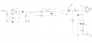
I don'get it, those caps are not in series...
Do you really mean that we can, with a single coupling cap, in a typical configuration like in the attached schematic, move C13 without impacting the equivalent capacitance seen by R13???
If so, can you elaborate?
Attachments
the situation I am explaining is considering only series connected DC blocking capacitors. They cannot be anything but series connected.those caps are not in series...
The Source has a medium quality DC blocking cap at it's output.
The MyRefC has a good quality DC blocking cap at it's input.
As far as the signal is concerned, these two DC blocking caps are in series.
If you build a Source without an optional bypass across it's DC blocking cap and you connect that to MyRefC without an optional bypass across it's DC blocking cap then the system sees the two DC blocking caps in series. The effect of this series connection is that the capacitance seen by the Source equipment changes and the capacitance seen by the Receiver equipment changes.
I am suggesting that the optional bypasses be added, or at least provision for, so that builders can listen to the three operational cases I outlined earlier.
As for your question on the effect of cable impedance to the system, I am not prepared to guess. You can, if you want.
Last edited:
Still going on...
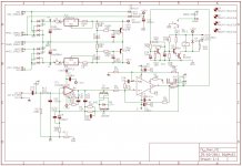
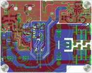
The project is alive and going on
I've had some help on the Costruire HiFi Italian forum about the LM318 PS (thanks Luka) so PCB and schematic are now complete.
I still have to test the PS (to be sure it's better than the original one) and any further suggestion is welcome.
After that I'll probably order some preliminary boards.
Attachments
Last edited:
- Status
- This old topic is closed. If you want to reopen this topic, contact a moderator using the "Report Post" button.
- Home
- Amplifiers
- Chip Amps
- My_Ref Fremen Edition - need help on PCB evaluation