half the rail voltage (40V DC) at Q1's drain.
The schematic of page 61 specify the work with the CCS , but it is 30 Volt rail voltage , not 40 or 60 . That version works and sounds (!) pretty good . I do not believe it will be scalable , for higher rail voltages , you'll need different values of R6 R10 and R7 .
")
Seems to have cut me off halfway...
Anyway, what I wanted to say was that I didn't want to get another custom wound transformer. Hence the 30-0, 30-0 (not 30-0-30) secondary windings. I used an 8 Ohm 50W at R5 instead and got pretty close but that would've defeated the purpose of the CCS. Pretty good sound though. I will take your advice of changing R6, R7 and R10. I would be grateful if you can tell me what voltages should be expecting at the IRFP240's gate? I am rather clueless at biasing unless it's a tube amp.
Thanks in advance.
30-0, 30-0 (not 30-0-30) secondary windings. I used an 8 Ohm 50W at R5 instead and got pretty close but that would've defeated the purpose of the CCS. I would be grateful if you can tell me what voltages should be expecting at the IRFP240's gate? I am rather clueless at biasing unless it's a tube amp.
Thanks in advance.
- with that secondaries it is possible to build 2 separate PS and have 40 volt or so each at Vdd ( and then go for dual mono power supply ) .
-As far as I understand it , from a previous Nelson's post , it is possible to raise the value of R5 , that it means to me ( if I 'm not wrong ) it can be set almost to zero ohm , but I didn't try it .
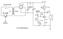
-The enanchement mode Mosfet IRFP240 , turns on typically at VGS= +3,5 Volt ( or little more ) .
In the example posted of CCS if Vdd is 30 volt , Voutput is half of it 15 volt , then R5 would have 1,6 volt across. The Gate of Q2 will be at : 15 + 1,6 + 3,5 = 20,1 volt in theory .
- Remember that the bias current is set by Q1, which is self biasing device , depending on R4 and its Vds .
PS : Later Will try to post another CCS based example with IRFP240 since i recall using for Q2 the IRFP 044 previously , and of course it has slightly different values settings for the bias .
Hi Steffano
Thank you for your reply. Yes, the amp is a dual mono design. I have used an 8 Ohm resistor at R5 but is this the way to do it?
Voltage at R4 is 1.8V = 1.8A@1 Ohm and I am getting all the voltages proper based on that current draw.
My questions are:
1. What is the purpose of R6, R7 and R10 and how do I use them effectively?
2. Am I supposed to get 20V DC (1/2 Vdd 40V DC) at Voutput which is at Q1's drain?
3. As mentioned above, can I change the value of R5?
Thanks again for your patience.
Hi Steffano
1. What is the purpose of R6, R7 and R10 and how do I use them effectively?
2. Am I supposed to get 20V DC (1/2 Vdd 40V DC) at Voutput which is at Q1's drain?
3. As mentioned above, can I change the value of R5?
1)The purpose of R6 , R7 R10 are to set 1/2 Vdd at the output , so yes for question 2)
3) yes
Hi Steffano,
Got it. Thanks.
Welcome .
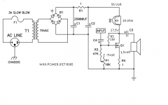
Below , in the attached schematic , I have another example of personal experiment , little feedback loop , negative voltages to set the working line .
During the listening I've found that carefully trimming p1 to obtain -Vgs = V on R4 the amp started to fly . While with differen values the sound is more boomy on the bass and less precise on the highs .
I wonder if this thing is effectively important or just the result of this particular implementation , considering also that my speakers are set up with a current source equalization .
(V at the drain of Q1 is 13,7 Volt.)
Thanks
Attachments
Last edited:
Stefanobilliani,
IS Q1 a R085, or the IXYS?
Also, is 1.68v over R4, or is that R?
I think your saying - measured vgs (measuring at gate and source) should be about the same voltage as measuring voltage across R4. (?)
Tea
Yes in this example it is IXYS . I did something similar with the R085 .
Yes for second question : 1,68 is the voltage across R4 .
so Vgs ( wich is negative ) is trimmed for the same voltage across R4 .
I don't imagine why , but the fine tuning gives instantly better sound .
The R085 is ... different thing , sound much better musically ( the bass much more articulated , the midrange sweet non agressive , highs good )but <maybe> a bit less easy to live with ... ( and here also don't know why ).
I might probably investigate better on the audio source , since I have very good computer software handy .
... and of course , the main difference could be the light bulb , and the loading lines . Infact I found in the IXYS case the light bulb to be equivalent to 22 ohm ; different in the R085, it goes to 15 ohm ...
Last edited:

Are the Gate and Source tied together with R4?
Have you managed to work it out?
No. I need one of the brainy one's on here to tell me if the diagram is showing an external or internal connection between G & S
. I need one of the brainy one's on here to tell me if the diagram is showing an external or internal connection between G & SAn externally hosted image should be here but it was not working when we last tested it.
No
An externally hosted image should be here but it was not working when we last tested it.
I'm sure the main man will be only too happy to help
schematic is soooooo simple
G&S are together on GND
I am VERY Simple!
Phew...! Well maybe after all this time, I can get it working
Thanks Zen Mod
- Home
- Amplifiers
- Pass Labs
- Pass "DeLite" Amp from BAF