@JPV -- I'm guessing you've never seen an emitter follower oscillate...
Of course an emitter follower can exhibith peaking because it presents an inductance as output impedance but this is true for any amplifier topology.
JPV
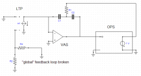
The loop gain around the output stage is, with the "global loop" back through the IPS broken
Code:( + C1) ------------------- ( + C2 C1 R1 ) s
times the gain of the output stage itself, so that is not correct. If all other feedback paths are in place it looks like in andy_c:s post and has a double-pole, single zero type response. See also the equation in my previous reply.
Are you talking of the main loop with beta attenuation to the input stage?
JPV
Hi wahab,
I'm afraid you are jumping too fast to conclusions. Increasing gm by a factor of 2 will indeed reduce IMD, of course. But decreasing RE will also increase the IPS non-linearity. Now, the question is which of the two mechanisms has the most impact?
E.
Hi, Edmond
Of course that the IPS is more loaded with TMC, since
the VAS+OPS gain is lower seen from the IPS output,
but presently, i have no idea of its significance order..
For the record, i did bias the LTP to 2mA total current,
that is 1mA in each half.
Current variation at the IPS output is 100uA, that is 10%,
while it is 4uA , 0.4% , for TPC.
Why would more feedback provided by the IPS be less efficient
than the same amount of gain brought by the VAS?..
Since all IMD products other than the one mentionned are
decreasing in proportion of the IPS increased gain, one can
deduct that its additionnal NFB is effective.
The fact that increasing the VAS gain also increased the slew rate
lead me to think that this distorsion is slew induced.
As to explicit the underliyng causeof this IMD, we can suppose that
this is due to the VAS+OPS being too slow in respect of the IPS,
rendering the IPS increased gain innefficient to cope with the said
distorsion..
Generaly, i got the best global result by pondering TMC with
a TPC network , and then getting rid of the remaining overshoot
with a lead compensation, although with caps values much lower
than in the exemples of Megajocke, as 1 to 2pF in serial
with a few KR is way enough,thanks to the already existing
TMC contribution.
cheers
w
Are you talking of the main loop with beta attenuation to the input stage?
JPV
I don't understand what you are referring to here.
It is, in a multiloop description, the minor loop enclosing both the VAS and output stage back into the VAS through R1. I approximated the VAS by an ideal opamp which is a good approximation at the frequency this loop crosses over.
Attachments
Last edited:
 YWN (aka syn08) has left the building.
Arguing about how much loop gain surrounds the output stage does not make your point - there is more to it.
I am afraid i disagree: the loop gain sims tell the whole story from my perspective.
For those who have the time and would like to explore further the component values i gave earlier may help; here:
http://www.diyaudio.com/forums/soli...lls-power-amplifier-book-112.html#post2407617
Last edited:
Hi Bob,
Well said. However, did you notice that he has used equal caps in the TMC compensation? This explains why he erroneously thinks that TMC is inferior to TPC. With such a bad choice of caps, of course TMC can't be competitive.
Cheers,
E.
That red herring again.
You can use any values you choose for your TMC network. Provided they are duplicated in the TPC arrangement (for the same unity gain frequency) my conclusions will remain valid.
After all let's not forget that you agree with my findings here:
http://www.diyaudio.com/forums/soli...terview-negative-feedback-69.html#post1163454
Last edited:
Provided that the amp is unconditionally stable (that is, the phase never dips under 180 degrees before the unity loop gain frequency is reached, so the amp is stable for all closed loop gains) I am not sure why Bob feels "nervous" about and what is the "added risk".
Good point!
A higher IMD could be explained by a higher output current of the IPS (tanh distortion). This assumption is supported by the fact that if I increase the tail current (and also increase the emitter resistors to maintain the same gm), I get a lower IMD figure.
E.
Hi, Edmond
On second thought, if you increase the LTP current, you mechanicaly
increase the slew rate, that s why i did also use the variable degeneration
route to check the cause of IMD.
cheers
Last edited:
Good point!
Well as Roberge is explaining in his book, although TPC is unconditionnally stable, it can become conditionnally stable in a describing function way when facing clipping or saturation. This non linear event can trigger jump resonnance which is very bad and exhibits hysteresis meaning that the entry condition is not the same as the exit one. TPC is still a powerfull technique but you must avoid saturation by all means.
JPV
I am afraid i disagree: the loop gain sims tell the whole story from my perspective.
For those who have the time and would like to explore further the component values i gave earlier may help; here:
http://www.diyaudio.com/forums/soli...lls-power-amplifier-book-112.html#post2407617
Mike,
For the life of me I just can't understand why YOU don't just go ahead and do it. Uuuggghhh!!!
Bob
Well as Roberge is explaining in his book, although TPC is unconditionnally stable, it can become conditionnally stable in a describing function way when facing clipping or saturation. This non linear event can trigger jump resonnance which is very bad and exhibits hysteresis meaning that the entry condition is not the same as the exit one. TPC is still a powerfull technique but you must avoid saturation by all means.
JPV
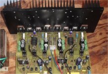
In an "unscientific way" , I put a traditional miller comp. amp up against the TMC one at the new years party. Since I am a prolific builder , I could care less about blown OP devices. We , at the party .. clipped , overloaded , actually tried to blow out 2 pairs of amplifiers. The traditional one sounded terrible well into clipping as it should .. we blew a fuse on them but everthing survived with a new fuse. The TMC enhanced blameless actually had a less fatiguing sound as it clipped. Neither amp had ANY hot devices in the IPS/VAS (the OPS was a nice hand warmer) no tweeters blew , no warm zobles. We tried to FRY these amps for the "hell of it". This is a good testament that Bob's amplifier examples are robust and reliable and that TMC does not detract from those strengths AT ALL. One amp we even shorted out at full power ... it actually survived with a blown fuse.

Below- the "sacrificial amp" , 80W...
OS
Attachments
the "spice tricks" are meant to illuminate not confound
I don't suppose a direct sim of robustness to added output delay will cause anyone to rethink?
As I stated earlier in this thread a sticking point seems to be people wanting to believe that the outer loop gain/phase margin Bode plot of TMC looking like CMC means you managed greater loop gain/distortion reduction - "for free"
I find it hard to believe the resistance to the TANSTAAFL principle among a engineering oriented community
Specifically I have pointed to Bode's Integral relations and BJ Lurie's work that shows how this "conservation law" for feedback is applied
My earlier output conductance sim clearly established that the added feedback is externally visible - simply by "tugging" on the output node you can tell TMC from CMC
the Bode Integral relations lead me to expect more feedback has a cost in loop gain slope and phase margin - the extra distortion reduction performance of TMC - is not "free"
Now I have another sim - this time I packaged up Bob's amp, bringing out the VAS connections so compensation can be seen as external components
I've added a pure delay to the output of the amp - between the loaded output and the normally output connected feedback components to sim variable "excess poles" - which Bob mentions in his book can be approximated as delay
To give a baseline I have a "CMC" amp on top and the TMC compensated amp on the bottom
I step the delay from 0 to 100 ns in 25 ns steps
You should see that the "simple Middlebrook" gain probe is in the "outer loop" in both sims - and "step 1: tau = 0" does make TMC look very similar to CMC as can be read from the cursors
however as output stage delay is added the crossover frequency jumps upward in the TMC sim and gain margin collaspes - not like your 1st order loop
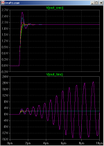
other things you can do with the sim - plot V(out_Xmc) in .AC to see the TMC peaking with added delay
replace the sine source with a small amplitude step (with ~ 1 us delay) and run a .tran (very high resolution 10 us, 1 ns t_step_max) - and see the TMC sim break into oscillation at higher delays
In sum: You Have been bitten by those inner loops - TMC is not as stable as CMC, the gain/phase measured in the outer loop is not informative in the TMC case
I don't suppose a direct sim of robustness to added output delay will cause anyone to rethink?
As I stated earlier in this thread a sticking point seems to be people wanting to believe that the outer loop gain/phase margin Bode plot of TMC looking like CMC means you managed greater loop gain/distortion reduction - "for free"
I find it hard to believe the resistance to the TANSTAAFL principle among a engineering oriented community
Specifically I have pointed to Bode's Integral relations and BJ Lurie's work that shows how this "conservation law" for feedback is applied
My earlier output conductance sim clearly established that the added feedback is externally visible - simply by "tugging" on the output node you can tell TMC from CMC
the Bode Integral relations lead me to expect more feedback has a cost in loop gain slope and phase margin - the extra distortion reduction performance of TMC - is not "free"
Now I have another sim - this time I packaged up Bob's amp, bringing out the VAS connections so compensation can be seen as external components
I've added a pure delay to the output of the amp - between the loaded output and the normally output connected feedback components to sim variable "excess poles" - which Bob mentions in his book can be approximated as delay
To give a baseline I have a "CMC" amp on top and the TMC compensated amp on the bottom
I step the delay from 0 to 100 ns in 25 ns steps
You should see that the "simple Middlebrook" gain probe is in the "outer loop" in both sims - and "step 1: tau = 0" does make TMC look very similar to CMC as can be read from the cursors
however as output stage delay is added the crossover frequency jumps upward in the TMC sim and gain margin collaspes - not like your 1st order loop
other things you can do with the sim - plot V(out_Xmc) in .AC to see the TMC peaking with added delay
replace the sine source with a small amplitude step (with ~ 1 us delay) and run a .tran (very high resolution 10 us, 1 ns t_step_max) - and see the TMC sim break into oscillation at higher delays
In sum: You Have been bitten by those inner loops - TMC is not as stable as CMC, the gain/phase measured in the outer loop is not informative in the TMC case
Attachments
Last edited:
Slew rate
Hi wahab,
In principle, you are right: the maximum SR is increased. But under the given circumstances, the signals are by no means limited by the max. SR:
IPS output current: 0.58mApp
VAS output current: 0.11mApp
These values are way below the tail current, respectively VAS-CCS. So I still believe that the IPS non-linearity is the culprit.
Cheers,
E.
Hi, Edmond
On second thought, if you increase the LTP current, you mechanicaly increase the slew rate, that s why i did also use the variable degeneration route to check the cause of IMD.
cheers
Hi wahab,
In principle, you are right: the maximum SR is increased. But under the given circumstances, the signals are by no means limited by the max. SR:
IPS output current: 0.58mApp
VAS output current: 0.11mApp
These values are way below the tail current, respectively VAS-CCS. So I still believe that the IPS non-linearity is the culprit.
Cheers,
E.
I don't suppose a direct sim of robustness to added output delay will cause anyone to rethink?
As I stated earlier in this thread a sticking point seems to be people wanting to believe that the outer loop gain/phase margin Bode plot of TMC looking like CMC means you managed greater loop gain/distortion reduction - "for free"
I find it hard to believe the resistance to the TANSTAAFL principle among a engineering oriented community
Specifically I have pointed to Bode's Integral relations and BJ Lurie's work that shows how this "conservation law" for feedback is applied
My earlier output conductance sim clearly established that the added feedback is externally visible - simply by "tugging" on the output node you can tell TMC from CMC
the Bode Integral relations lead me to expect more feedback has a cost in loop gain slope and phase margin - the extra distortion reduction performance of TMC - is not "free"
Now I have another sim - this time I packaged up Bob's amp, bringing out the VAS connections so compensation can be seen as external components
I've added a pure delay to the output of the amp - between the loaded output and the normally output connected feedback components to sim variable "excess poles" - which Bob mentions in his book can be approximated as delay
To give a baseline I have a "CMC" amp on top and the TMC compensated amp on the bottom
I step the delay from 0 to 100 ns in 25 ns steps
You should see that the "simple Middlebrook" gain probe is in the "outer loop" in both sims - and "step 1: tau = 0" does make TMC look very similar to CMC as can be read from the cursors
however as output stage delay is added the crossover frequency jumps upward in the TMC sim and gain margin collaspes - not like your 1st order loop
other things you can do with the sim - plot V(out_Xmc) in .AC to see the TMC peaking with added delay
replace the sine source with a small amplitude step (with ~ 1 us delay) and run a .tran (very high resolution 10 us, 1 ns t_step_max) - and see the TMC sim break into oscillation at higher delays
In sum: You Have been bitten by those inner loops - TMC is not as stable as CMC, the gain/phase measured in the outer loop is not informative in the TMC case
Nice work, JCX. This is the kind of analysis and direction we all learn from. Sometimes there is no free lunch, but sometimes there is a tastier one
.Let me chew on this for awhile.
Cheers,
Bob
Mike,
For the life of me I just can't understand why YOU don't just go ahead and do it. Uuuggghhh!!!
Bob
Mr. Cordell,
As someone who's bought your book (and the first, fourth and 5'th editions of Mr. Self's ), read both this and the negative feedback threads start to finish, and found the vast majority of the discussion to be extremely educational...I completely understand your frustration. I am extremely confused by the points that Mike is trying to make, and his method of communication.
I just hope it isn't so frustrating to you and Mr. Stuart that the valuable discourse on compensation and amplifier design in general is shut down.
So, I thank you for your patience and your contributions to the DIY community.
Scott
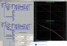
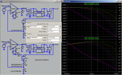
This sim moves the simple Middlebrook gain probe to the “inner” feedback loop, measuring all of the gain around the output stage
I think you can see it is a much more useful way to view the stability margin of TMC
To look at the phase margin numbers with the added delay we have to convert the delay time into phase – since delay has linear phase with frequency the phase depends on the frequency
For the CMC loop 100 nS delay at the 977KHz gain intercept is:
100ns * 977kHz * 360 degrees = 35 degrees added phase shift
the cursor reading gives 77.8 degrees phase margin for the CMC at 0 delay,
42.6 degrees at 100 ns (append @5 to both V in the waveform formula, ie V(d_cmc)@5/V(b_cmc)@5)
77.8 - 35.2 = 42.6 which agrees with the idea that the added delay is a fair measure of phase margin
the numbers clearly don’t work so neatly in the outer loop gain/phase plot of TMC because the gain intercept is a moving target
the Inner loop Bode gain/phase measurement of TMC below Is well behaved and we can do the same calculation:
100ns * 1.69MHz * 360 = 60.8 degrees added phase shift
the cursor reading gives 58.7 degrees phase margin for the CMC at 0 delay,
-2 degrees at tau = 100 ns, step 5
58.7 – 60.8 = -2.1 which again agrees and predicts that the TMC loop will be unstable with 100 ns added delay – as the tran sim pic above shows
as a further check note that 100nS is just over the 0 degree line and the previous step at 75ns delay has poor but positive phase margin – and the tran sim shows it does settle out instead of oscillate
(Thanks to Mike Engelhardt of Linear Technology – you may have noticed the stepped waveform colors didn’t agree in the previous post Bode plot but they do match in this sims pic – the 1st time I’ve had a bug fixed over lunch! )
I assume anyone wanting to verify can mod the .asc in my previous post
Attachments
In an "unscientific way" , I put a traditional miller comp. amp up against the TMC one at the new years party. Since I am a prolific builder , I could care less about blown OP devices. We , at the party .. clipped , overloaded , actually tried to blow out 2 pairs of amplifiers. The traditional one sounded terrible well into clipping as it should .. we blew a fuse on them but everthing survived with a new fuse. The TMC enhanced blameless actually had a less fatiguing sound as it clipped. Neither amp had ANY hot devices in the IPS/VAS (the OPS was a nice hand warmer) no tweeters blew , no warm zobles. We tried to FRY these amps for the "hell of it". This is a good testament that Bob's amplifier examples are robust and reliable and that TMC does not detract from those strengths AT ALL. One amp we even shorted out at full power ... it actually survived with a blown fuse.
Below- the "sacrificial amp" , 80W...
OS
Hi OS,
Nice report! Sounds like you had fun! That's encouraging to hear that the TMC design sounded less fatiguing in clipping.
Can we deem these results credible in spite of the amount of liquor that was probably flowing?
Cheers,
Bob
Bridged TMC
Some of you may recall that I introduced what I called Bridged-T Compensation (BTC) in Chapter 9 of my book, figures 9.4 and 9.5. It is TPC with a small capacitor bridging the "T", connecting directly from the VAS output to the VAS input. This capacitor that I will call C3 here is no more than a couple of pF. It eliminates the very large peak that we have seen here in the TPC loop gain characteristic that often occurs in the audio band, making the TPC loop gain characteristic look much better behaved (see Figure 9.5 in my book). Although it is not clear that such a peak causes serious problems in the closed loop response, it seems to me that it cannot be a good thing.
Accompanying this peak is the sudden phase drop to a value not far from 360 degrees, which also causes some consternation. The bridging capacitor also pretty much cures this.
At the same time, the introduction of the bridging capacitor does not increase distortion by more than 10%.
We have also seen here that if one examines the total loop gain seen by the output stage in a TMC design, we also see pretty much the same peak. Placing a small bridging capacitor across the TMC network in the same fashion as BTC yields the same benefit in what we might now call bridged TMC (BTMC).
The attached zip file contains a folder of six ready-to-run TMC loop gain analyses, three for TMC and three for BTMC, where a 0.5 pF bridging capacitor has been added.
The amplifier is the same one that I have presented earlier, but it has been further loaded by 0.1uF and 1 ohm in series to reduce phase margins.
In one pair of simulations the conventional global feedback loop is shown with the loop opened. For this loop, the gain crossover is at 1.3 MHz with a phase margin of 55 degrees and a gain margin of 20 dB (roughly the same with and without the bridging capacitor)
In another set of simulations the local compensation loop that encloses the output stage and VAS is analyzed for loop gain. For this local loop, the gain crossover frequency is 750 kHz with a phase margin of at least 73 degrees and a gain margin of at least 26 dB.
In a third pair of simulations the total loop gain seen by the output stage, due to both the global and local loops, is shown. For the total loop gain enclosing the output stage, the gain crossover frequency is 1.6 MHz with a phase margin of 29 degrees and a gain margin of 22 dB. Bear in mind the challenging load being placed at the output of this amplifier.
Without the bridging capacitor, the phase dip in the TMC total output stage loop gain goes down to a margin of 10 degrees and is accompanied by a loop gain peak of 15 dB. With a value of 0.5pF, the phase dip only goes down to a margin of 27 degrees and there is no longer any peak in the loop gain characteristic. At 1pF, the bridging capacitor keeps the phase from dipping to less than amargin of 37 degrees.
The bottom line is that the addition of the small bridging capacitor can improve the behavior of both TPC and TMC insofar as the loop gain peaking and (in my mind perilous) mid-band phase dip.
Please bear in mind that this technique, and these results, do not by themselves make a case for or against TMC vs. TPC.
Cheers,
Bob
Attachments
Some of you may recall that I introduced what I called Bridged-T Compensation (BTC) in Chapter 9 of my book, figures 9.4 and 9.5. It is TPC with a small capacitor bridging the "T", connecting directly from the VAS output to the VAS input. This capacitor that I will call C3 here is no more than a couple of pF. It eliminates the very large peak that we have seen here in the TPC loop gain characteristic that often occurs in the audio band, making the TPC loop gain characteristic look much better behaved (see Figure 9.5 in my book). Although it is not clear that such a peak causes serious problems in the closed loop response, it seems to me that it cannot be a good thing.
Bob
Hi, Bob
In fact, a cap as low as 0.2pF is enough to get rid of the TPC OL gain
peaking, so in real implementation, it s unprobable that such peakings
occur as the parasistic layout and components leads caps are enough to
create this cap, while not decreasing available gain.
Though, as soon as the loop is closed, the usual step response
peaking will remain, since the TPC loop becomes then dominant.
As i already pointed, a TMC network pondered with a TPC one
is generaly the optimmum in respect of the global behaviour,
although i m not still sure if there isnt undesirable by products.
cheers,
w
Last edited:
- Home
- Amplifiers
- Solid State
- Bob Cordell's Power amplifier book