LP filter
Hi Joakim,
All the time I was waiting for such a 'solution', but certainly not from you. I'm sorry to say so, but for someone of your stature, you should know better. With a LP filter between the signal source (e.g. a square wave) and the amp, the only thing you have altered is the spectral content of the test signal, while the characteristics of the amp proper (e.g. the step response) haven't changed at all. The LP filter just hides the overshoot, but if you apply an appropriate test signal to the amp itself, it's still there. It's a fake solution. Sorry.
Cheers and happy new year everyone!
E.
edit: What about a LP filter between the amp-output and the speaker?")
Hi Edmond,
[snip]
I realized later that there is another practical way to implement a TMC equivalent TPC circuit which does not require a lead network in the feedback path, and that is to select another TPC VAS transimpedance Z' with tau3' = tau2 instead of tau1.
Then a lag network with transfer function (s tau1 + 1)/(s tau2 + 1) is inserted in the input signal path to the LTP instead of the lead network in the feedback path to give the same Vd.
Vd = Z' * I3' = D' (s tau3' + 1)/(s^2) gm [(s tau1 + 1)/(s tau2 + 1) Vin - Vfb/A]
which also becomes, because tau3' = tau2,
Vd = Z' * I3' = D' gm [ (s tau1 + 1) Vin - (s tau2 + 1) Vfb/A ]/(s^2).
But after that, you may want to consider removing the zero at tau1, which shows up in the closed loop response, by inserting a standard low-pass filter instead with transfer function 1/(s tau2 + 1). If the impedance of the source feeding the power amplifier is low or known this could just be the standard input slew rate/RF ingress limiting filter.
Cheers and happy new year everyone! (Skål och gott nytt år till er alla!)
Hi Joakim,
All the time I was waiting for such a 'solution', but certainly not from you. I'm sorry to say so, but for someone of your stature, you should know better. With a LP filter between the signal source (e.g. a square wave) and the amp, the only thing you have altered is the spectral content of the test signal, while the characteristics of the amp proper (e.g. the step response) haven't changed at all. The LP filter just hides the overshoot, but if you apply an appropriate test signal to the amp itself, it's still there. It's a fake solution. Sorry.
Cheers and happy new year everyone!
E.
edit: What about a LP filter between the amp-output and the speaker?
Last edited:
Seems it is clear that Joakim knows exactly what he is doing and is even providing the circuit analysis to prove it; very nice work! He is making it clear that by including the input filter which is often part of an amplifier it is possible to eliminate the overshoot and this is important with regard to how the amp will behave in practice, in real use. In fact, it is unlikely that any real audio signal will ever have high enough rise time to show the overshoot. However, you are correct that if we are looking at overshoot as an indication of stability, then the input filter should be avoided, since it is outside of the feedback loop, so that we apply a proper signal to see the real wide-band behavior of the amp.
Obviously the input filter has no impact on gain or phase margin of the amp being outside of the loop.
Obviously the input filter has no impact on gain or phase margin of the amp being outside of the loop.
That's no sim, that are schematics without any useful comment. No graphs, no distortion figures, no phase margins, step response, etc.
...and here are the results:
http://www.diyaudio.com/forums/soli...terview-negative-feedback-69.html#post1163433
Moreover Edmond actually agrees with me here:
http://www.diyaudio.com/forums/soli...terview-negative-feedback-69.html#post1163454
http://www.diyaudio.com/forums/soli...terview-negative-feedback-69.html#post1163454
TMC vs TPC
I tried a simple analysis using the method developed by Roberge ( minor loop) and very well explained in Lundberg's tutorial.
In the TMC page annexed you will see that the loop gain is very well approximated by a firs order system as explained many times by E Stuart and B Cordell.
To analyse the distortion aspect I concentrated on the distortion generated at the output that can be modeled by a perturabation source added ( Vd).
We can analyze this in two steps: first when C2 impedance is large with respect to R and then when R is short circuited by C2.
An easy approach is to put Vin =0 and analyze the input output circuit where Vd is the input, the closed loop gain is then attenuation of the distortion.
The voltage distortion Vd can be moved out of the minor loop by dividing it by the loop gain of this minor loop then we can again attenuate it by the major loop loop gain. But in this one we can introduce the approximation of the minor loop closed loop gain as explained by Lundberg.
When R is conducting we have two attenuation loops and when R is short circuited we have a normal Miller loop.
The same approach is applied at TPC.
What can we conclude?
Both methods have the same output distortion attenuation at low frequencies but TMC can go higher in frequency. The zero in TPC ( 2RC ) may not be put to much to the right in the Bode plot otherwise the poles from the main amplifier will influence the phase shift of the loop gain and then the stability is at risk.
On the contrary, with TMC we have one more degree of freedom. We can adjust R to move the pole to the right while keeping the stability unchanged. We could then in theory gain some attenuation of the distortion without risking stability.
I hope I didn't make any mistake and your comments are welcome.
JPV
Attachments
enlightening?
Very enlightening!
Normally, we put a schematic (544) and the results (682) in one and the same post, instead of 138 posts behind it.
Except that the FB around the OPS is the same in both cases, I do NOT agree with your assertions.
edit: Having a closer look at your schematics, WTF what is the lead compensation (R29=2k2 and C11=68p) doing there in the TMC version?
Also, the lead compensation for the TPC is wrong. What a mess!
...and here are the results:
http://www.diyaudio.com/forums/soli...terview-negative-feedback-69.html#post1163433
Very enlightening!
Normally, we put a schematic (544) and the results (682) in one and the same post, instead of 138 posts behind it.
Moreover Edmond actually agrees with me here:
http://www.diyaudio.com/forums/soli...terview-negative-feedback-69.html#post1163454
Except that the FB around the OPS is the same in both cases, I do NOT agree with your assertions.
edit: Having a closer look at your schematics, WTF what is the lead compensation (R29=2k2 and C11=68p) doing there in the TMC version?
Also, the lead compensation for the TPC is wrong. What a mess!
Last edited:
All the time I was waiting for such a 'solution', but certainly not from you. I'm sorry to say so, but for someone of your stature, you should know better. With a LP filter between the signal source (e.g. a square wave) and the amp, the only thing you have altered is the spectral content of the test signal, while the characteristics of the amp proper (e.g. the step response) haven't changed at all.
But it's not just an ugly "make the signal slow enough to not show the overshoot" hack but an exact cancellation of the VAS zero, and replacement with another if you want which makes the signal-to-output and feedback-to-output response (and thus closed-loop response) exactly the same for all three front end configurations (TMC, TPC+feedback lead and TPC+input lag).
The overshoot in the step response of the new TPC configuration without input filter doesn't stem from lower stability margin than the TMC or TPC+lead version but that the forward path zero falls at the same frequency as the feedback one. By increasing the VAS zero time constant from tau1 to tau2 you got back the phase margin that the lead network earlier gave you.
I'm sure you know this already, but it's not only a low stability margin that gives you overshoot. If you have zeros in the response it is also possible even if all poles are real. Take for instance an example where you put a lead network (shelving hipass) before the amplifier. You can make it overshoot but this doesn't mean that you have decreased the stability margin of the amplifier, obviously.
The only difference between the two configurations is the signal handled by the LTP. Canceling the forward path zero with a LP filter on the input, by the way, gives a nice heavily overdamped second order response without zeros (so it's close to first order) if tau2 is long enough compared to the gain crossover frequency.
Cheers!
Last edited:
What do you mean by 'Lumbatomized'?
Hi, Edmond
Surely that he means that some (necessary?) entertainement
has been brought in this thread....
cheers
Sure, but by whom? Perhaps Mike?
Although he is sometimes quite vindicative, i m afraid that
even he promotes lead phase circuits, in the discussed matter
he s lagging and lacking compared to our usual suspect....
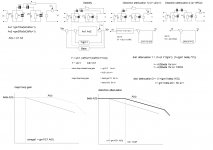
More seriously, some sims about step response of TPC/TMC.
As always, a blameless as the necessary pig...
The sim show the influence of the VAS loading capacitor
in respect to a step.
At the rising, everything is good, with TPC having higher slew rate.
At the fall, the picture change completely, with TPC showing a brutal
change in the signal slope...
Of course, this is due to the assymetrical nature of the amp,
as a symmetrical differential will generaly remove most of this
effect since the two sides can increase the current if necessary...
I can only conclude that compensation must predate the design,
as it must be designed from the start according to the choosen
compensation scheme...
cheers
w
Attachments
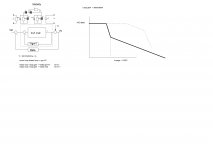
Next is a very interesting sim about intermodulation distorsion.
I proceeded to use the same components for the compensation network.
The signal is 19+20KHZ 1/1 ratio , the output level is 34V peak 8R load.
As can be seen, IMD is higher with TMC for the lateral frequencies ( 18/21KHZ)
as well as, logicaly, for the 1KHZ residual.
Increasing the LTP gain by reducing the degeneration, did reduce
all intermodulation products accordingly to the increased NFB,
but oddly, the mentionned frequencies, i.e, 1KHZ and 18/21KHZ
didn t see their level reduced, meaning that something else than
a lack of NFB was at work;
Reducing by a factor àf two the cap connected to the vas input
and thus increasing the gain but also the slew rate did yield
a spectacular reduction in the reluctant frequencies level, meaning
that IMD is a slew induced distorsion in that case, and namely
originating in the VAS..
As a consequence, and as already stated, compensation choices inerhently
mandate an adequate design as acting on the other way is putting the cart
at the wrong end..
Attachments
Last edited:
Both methods have the same output distortion attenuation at low frequencies but TMC can go higher in frequency.
Hi.
Not by much I'm afraid because it's hopefully the output stage that is the biggest problem up there and the properties of the loop gain around the output stage, counting all loops enclosing it, is therefore the most interesting parameter IMO.
The feedback through the R in the TMC network does indeed bypass the LTP giving it a little advantage when it comes to phase margin in the output stage loop for the same distortion reduction, but the LTP can easily be made fast enough for it not to matter one way or the other.
The loop gain around the output stage in the TMC configuration becomes, if I didn't copy this incorrectly from my notes,
G_loop(s) = G(s) D (gm / A) (s tau2 + 1) / (s^2)
where
* G(s) is the output stage and load transfer function
* D = 1 / (R C1 C2)
* gm is the LTP transconductance
* A is the feedback divider ratio
* tau1 = (C1+C2) R
* tau2 = tau1 + (A / gm)
This holds for frequencies sufficiently below the VAS local loop crossover frequency, above where it runs out of DC gain and assuming the input stage is fast. See post 1220 for more details and schematics used for the derivation. C1 is the capacitor on the input side of the VAS here. Post 1262 continues by deriving the the relationship between the inputs and output of the front end.
Last edited:
Hi.
Not by much I'm afraid because it's hopefully the output stage that is the biggest problem up there and the properties of the loop gain around the output stage, counting all loops enclosing it, is therefore the most interesting parameter IMO.
The feedback through the R in the TMC network does indeed bypass the LTP giving it a little advantage when it comes to phase margin in the output stage loop for the same distortion reduction, but the LTP can easily be made fast enough for it not to matter one way or the other.
The loop gain around the output stage in the TMC configuration becomes, if I didn't copy this incorrectly from my notes,
G_loop(s) = G(s) D (gm / A) (s tau2 + 1) / (s^2)
where
* G(s) is the output stage and load transfer function
* D = 1 / (R C1 C2)
* gm is the LTP transconductance
* A is the feedback divider ratio
* tau1 = (C1+C2) R
* tau2 = tau1 + (A / gm)
This holds for frequencies sufficiently below the VAS local loop crossover frequency, above where it runs out of DC gain and assuming the input stage is fast. See post 1220 for more details and schematics used for the derivation. C1 is the capacitor on the input side of the VAS here. Post 1262 continues by deriving the the relationship between the inputs and output of the front end.
I do not understand your arguments.
TMC as TPC are minor loop compensation techniques
With respect to LTP they have both the same effect except for loading.
Circuits like these are very complex for analytical investigation and a mistake is quickly done.
In a two voltage gain stage, the forward path ( including LTP and output stage ) is modeled by its two main poles. This is done by all the main authors in the field when they analyze such a system ( Roberge, Sansen, Solomon, Lundberg, Gray). The key point for stability is to manage the dynamic below unity loop gain so that the influence of non dominant poles are not too detrimental at unity loop gain.
The analytical approach used and advocated by top players in the field has the beauty of keeping it simple and avoid the writing of node equations that makes it abstruse even in this simple case.
What this method shows is that the stability analysis must use a different loop transmission than the one attenuating the output stage distortion in case of TMC at low frequencies. In TPC the loop gain for stability is the same as the loop gain for attenuation.
Before arguing with different equations, I would appreciate to understand what is wrong with my method and derivation or which errors I have made in the derivation ( it is always possible).
To quote an author: "it greatly simplifies and generalize the analysis and design of opamp compensation networks. Intuition and insight into the solution are gained by using these feedback techniques".
Thanks for comments
JPV
wrong TMC circuit
Results? The step response and distortion figures are missing.
Never mind, as the comparison is invalid anyhow.
Rather embarrassing, I would say!
...and here are the results:
http://www.diyaudio.com/forums/soli...terview-negative-feedback-69.html#post1163433
Results? The step response and distortion figures are missing.
Never mind, as the comparison is invalid anyhow.
Rather embarrassing, I would say!
IMD
Hi Wahab,
I've observed the same disastrous effects with TPC. However, you can get rid of it by reversing the capacitor ratio. So, instead of 1:5, use 5:1, just as advocated by Harry Dymond. The downside of this remedy is slightly more distortion, THD and IMD as well.
Indeed, these IMD figures are very interesting. The funny thing is that regarding TMC, THD is slightly lower and IMD is slightly higher compared to TPC. A higher IMD could be explained by a higher output current of the IPS (tanh distortion). This assumption is supported by the fact that if I increase the tail current (and also increase the emitter resistors to maintain the same gm), I get a lower IMD figure.
If I use a 5:1 capacitor ratio for the TPC case (and equal tail currents), then I get roughly the same IMD.
>but oddly, the mentioned frequencies, i.e, 1KHZ and 18/21KHZ didn't see their level reduced,
Hmm.... I did not observe this oddity. Due to different circuits and/or methods?
Cheers,
E.
[snip]
More seriously, some sims about step response of TPC/TMC.
As always, a blameless as the necessary pig...
The sim show the influence of the VAS loading capacitor in respect to a step.
At the rising, everything is good, with TPC having higher slew rate.
At the fall, the picture change completely, with TPC showing a brutal change in the signal slope...
Of course, this is due to the asymmetrical nature of the amp, as a symmetrical differential will generally remove most of this effect since the two sides can increase the current if necessary...
I can only conclude that compensation must predate the design, as it must be designed from the start according to the chosen compensation scheme...
cheers
w
Hi Wahab,
I've observed the same disastrous effects with TPC. However, you can get rid of it by reversing the capacitor ratio. So, instead of 1:5, use 5:1, just as advocated by Harry Dymond. The downside of this remedy is slightly more distortion, THD and IMD as well.
Next is a very interesting sim about intermodulation distortion.
I proceeded to use the same components for the compensation network. The signal is 19+20KHZ 1/1 ratio , the output level is 34V peak 8R load. As can be seen, IMD is higher with TMC for the lateral frequencies (18/21KHZ) as well as, logically, for the 1KHZ residual.
Increasing the LTP gain by reducing the degeneration, did reduce all intermodulation products accordingly to the increased NFB, but oddly, the mentioned frequencies, i.e, 1KHZ and 18/21KHZ didn't see their level reduced, meaning that something else than a lack of NFB was at work;
Reducing by a factor àf two the cap connected to the vas input and thus increasing the gain but also the slew rate did yield a spectacular reduction in the reluctant frequencies level, meaning that IMD is a slew induced distortion in that case, and namely originating in the VAS..
As a consequence, and as already stated, compensation choices inherently mandate an adequate design as acting on the other way is putting the cart at the wrong end..
Indeed, these IMD figures are very interesting. The funny thing is that regarding TMC, THD is slightly lower and IMD is slightly higher compared to TPC. A higher IMD could be explained by a higher output current of the IPS (tanh distortion). This assumption is supported by the fact that if I increase the tail current (and also increase the emitter resistors to maintain the same gm), I get a lower IMD figure.
If I use a 5:1 capacitor ratio for the TPC case (and equal tail currents), then I get roughly the same IMD.
>but oddly, the mentioned frequencies, i.e, 1KHZ and 18/21KHZ didn't see their level reduced,
Hmm.... I did not observe this oddity. Due to different circuits and/or methods?
Cheers,
E.
Last edited:
 I've deleted some personal sniping. Keep to technical arguments without the personal characterizations.
Never mind, as the comparison is invalid anyhow.
How is the comparison invalid?
Homework for you perhaps?Results? The step response and distortion figures are missing.
- Home
- Amplifiers
- Solid State
- Bob Cordell's Power amplifier book