A further update on the Sweet Peach SRPP project!
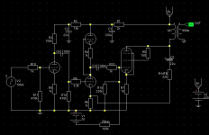
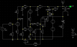
The input tube is now a single 6N2-EV with a voltage of about 320 with a 100K anode and a 1k resistor, the SRPP tubes are 6N6p with 190V on the (lower) plate from a supply of 375V. 8.5mA Idle current. The main supply is now dragged down to 420V ad the GU50s are currently in triode mode.
SRPP is fairly easy and neat - the LHS (RHS from below) tube is the lower triodes, the RHS one is the top triodes. I started with the lower tube only and used two 22K resistors to run until I installed the extra heater transformer. This is a compact (and very very cheap) potted 6VA 6V one that supplies the heater for the top SRPP tube only. The heater pin 5 is then wired to a cathode via a 220k resistor just to get it's voltage in the right ballpark.
Some more caps need to be bypassed but note the B+2 cap is now 120u (from a previous 22uF). The feedback caps at 22uF are the weak point now - I think I have around 8.5dB of feedback from the GU50 plate to the driver tube, I.e. it will reduce a 4V output to a 1.5V output when connected.
The SRPP method I used allowed me to directly compare before/after of the SRPP vs Common cathode. The SRPP gave more gain, more air and better dynamics - overall a considerable improvement was noted after the 2nd tube was added. Also I have not managed to clip it with this driver, whereas when I tried a single pentode (6J51p) driver it clipped easily (and badly).
The two VR tubes are for supplying the screens of the GU50s for pentode mode. They oscillate if you actually use them so they are buffered by an IRF730 source follower with a 5V protection zener from source to gate (I didn't have a 12V one on me, max gate voltage is +/- 20V).
The next task when time permits is to use the 255V grid voltage to run the GU50 in pentode mode. Not sure about this as the bias changes from c. 70V to c. 20V - thus bringing us closer to Vgk = 0V and the badness that entails.
I also have to test it on my best speakers - rather than the test ones in the workshop!
Thanks go to Wavebourne for some sensible pointers and useful answers.
Attachments
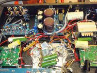
Just as a point of information to those Peach owners who have replaced their caps, there are two extra electrolytic coupling caps on the circuit board between/on the selector switch and volume control.
It is a 1K resistor in series with a small electro cap, per channel, just after the selector switch. I found them while probing with a mutimeter. I left the resistor in there but shorted out the caps by bridging the top of the PCBs. I can't actually get the knobs off so that board has to stay there for the moment - doh!
It is a 1K resistor in series with a small electro cap, per channel, just after the selector switch. I found them while probing with a mutimeter. I left the resistor in there but shorted out the caps by bridging the top of the PCBs. I can't actually get the knobs off so that board has to stay there for the moment - doh!
GU50 in pentode mode
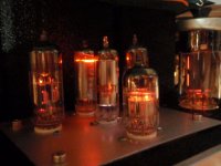
Finally got The Peach into pentode mode on the GU50s.
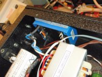
This involves driving a regulated G2 voltage of around 255V, which I tried before with some VR tubes - but every time I loaded them even a tiny bit they started oscillating - anything from 500Hz to 50kHz, which is easy to spot if you have a scope - but tricky without. Now I test everything with a scope and now it's very clean.
To stop the VR tube oscillations I used one of Wavebournes circuit ideas and put an IRF730 source follower in. It doesn't even need a heatsink and sits on a tiny bit of veroboard (the tab is live).
If you just connect up G2 you turn off the tube as well, as the usual 70V bias now changes to about 20V or so, so the peach needs the two earth side resistors on the bias circuit shorting out so one can re-bias.
With the current circuit B+ is at 420V, GU50 bias is at 60mA and there is only feedback between the GU50 and SRPP driver, plus local, no cathode capacitors are used. I still have a few electro caps to bypass but already it is showing massive promise. Pentode mode sounds better too, and I think this is because:
1) There is feedback around the pentode so output impedance is still low
2) The driver has to swing less volts, which makes it more linear
3) After drilling holes for VR tubes, getting the IRF730 mosfet etc I really want it to")
The only mods to do now are:
1) A little circuit tidying
2) Protection for the VR tubes/G2 voltage
3) Cap bypassing
4) Perhaps split the middle SRPP resistor to take output from the middle
5) Reference G2 to the cathodes, not ground
6) Try the 6N1p-ev, 6N2p-ev and 6N23p-ev in place of the 6N6p as SRPP tubes
Finally got The Peach into pentode mode on the GU50s.
This involves driving a regulated G2 voltage of around 255V, which I tried before with some VR tubes - but every time I loaded them even a tiny bit they started oscillating - anything from 500Hz to 50kHz, which is easy to spot if you have a scope - but tricky without. Now I test everything with a scope and now it's very clean.
To stop the VR tube oscillations I used one of Wavebournes circuit ideas and put an IRF730 source follower in. It doesn't even need a heatsink and sits on a tiny bit of veroboard (the tab is live).
If you just connect up G2 you turn off the tube as well, as the usual 70V bias now changes to about 20V or so, so the peach needs the two earth side resistors on the bias circuit shorting out so one can re-bias.
With the current circuit B+ is at 420V, GU50 bias is at 60mA and there is only feedback between the GU50 and SRPP driver, plus local, no cathode capacitors are used. I still have a few electro caps to bypass but already it is showing massive promise. Pentode mode sounds better too, and I think this is because:
1) There is feedback around the pentode so output impedance is still low
2) The driver has to swing less volts, which makes it more linear
3) After drilling holes for VR tubes, getting the IRF730 mosfet etc I really want it to
The only mods to do now are:
1) A little circuit tidying
2) Protection for the VR tubes/G2 voltage
3) Cap bypassing
4) Perhaps split the middle SRPP resistor to take output from the middle
5) Reference G2 to the cathodes, not ground
6) Try the 6N1p-ev, 6N2p-ev and 6N23p-ev in place of the 6N6p as SRPP tubes
Attachments
Last edited:
Hi Globulator!
I'm new in here, I like your " sweet Sugar " mod. I just bought my SP FU-50 couple months ago and I replaced with all Russian tubes. Everything else are original.
I tried to use your mod to modify my SP FU-50 but i don't know which parts i'm gonna buy.
Can you email me a list of all parts ? my email is: hhuuthuan@yahoo.com
BTW, you wrote 1k, 2.2k 5.6k resistors, is that mean 1 ohm, 2.2 ohm and 5.6 ohm ?
thanks a lot for your help..
~Tom
Hi Tom,
1k = 1000ohms, 2.2k = 2200ohms (the k means x 1000).
These are the only parts you need as I recall.
My current mod sounds better however (although more difficult!), I think because it removes the transformer and input tube from the feedback circuit and makes the transformer work better by presenting a low impedance drive to it.
What is your electronics experience?
If it is small - you may find the best value mod being to use a 6N6p in the centre tube position (The old 6N1p position).
Sounds good Tom, read the safety thread at the top of the forum too. The peach is a good amp to learn new stuff with because the SE design is very simple.
The major sound enhancement to the Sweet Peach is actually very simple, to change all the red 'Wima' capacitors.
You can just short out the tiny ones at the front, but the other 4 need replacing with genuine parts - any Polypropylene type of 450V or higher rating will be fine. The sound improvement with this change is dramatic! I think the supplied 'Wima' caps are fake or rejects.
You do not need to remove the PCB - that PCB is 'upside down' so the solder side is also the component side, just use a decent soldering iron and be quick.
Globulator,
It sounds as though you have been on quite a journey with your SP FU-50. When you have completed the final items on the to-do list will you consider publishing a consolidated description of all your mods? I think I will buy one and muck about with it and it would be great to get your overall impression of your mods and their relative effect. In any event, I really enjoy your posts.
Cheers
Casey
Hey Guys my mums wants a amp. I wanted something pretty and reliable. Therefore not one of my amps. But where on 240 volts over here despite the claims of hilly audio I believe there going to run hot and over voltage and eventually burn out on 240. I have tried to run 220 trans before. It don t work. Can anyone confirm this? Anyone see a 240volt tap In there when they pulled the cover off. Its a strange inefficient circuit BTW. I Prolly would run a axy srpp or e180f pentode driver with Eliniear feedback. I think I will grab one of my failures out the work shop the prettiest one and fix it up for her instead. Unless you guy can report a 240volt tap present
Hello folks,
Just joined the forum as a complete novice with tubes. I've been involved in hifi for many years but only just ventured into tubes with a small but beautifully constructed Chinese EL84 pp amp of about 5wpc. As a follow up I'm looking at the Sweet Peach SE with EL34. Trying to follow the various posts about this amp, it seems that as delivered it doesn't sound the best and can be improved by various tweaks.
I'm sure the old hands will groan at my questions, but in the end, I'd rather listen than fiddle; I don't have the knowledge after all. However, if it takes a few mods that a tyro like me can easily do to improve the sound, then I'm up for it...
I'm curious about making the pentode work in triode mode. It seems an easy mod, but I don't even know if the tube pin count is viewed from underneath or above the tube. Intuitively it's underneath...
It's been mentioned that various electrolytics can be swapped out for film caps, but then electrolytics are polarized, and I assume that film caps are not, so what's the go there?
I'm sure I'll have other questions but this will do for now..
Oh, incidentally I found an EL34 SE amp on Aliexpress which is cheap, looks like a kit, has a small parts count, big iron and point to point. I enquired and was told that it is indeed a kit, but for an extra $50 can be delivered fully built. Sounds like a bargain to me, and point to point means I could mod the thing more easily than PCB. P2P soldering just seems "right" for tube amps and I really like the idea of this one over the much better looking but more costly Sweet Peach. The price point also means that if my mods go south, I would lose less $$.
Just a thought...
Martin
Hi Guys,
I have ordered my sweet peach fu50, still got sometimes to wait for the shipment.. but I am already planning to replace the FU-50 with ry-50 or GU-50. Would anyone know if I need to fine tube the bias after changing to ry-50/GU-50?
Also, has anyone tried the 5670 as replacements to the 6N3? Any good?
Cheers,
ak
Hi guys, I am very new here. I got a Sweet Peach EL34 for my birthday. Now I want to change the originals valves with a couple of matched JJ EL34. DO I need to re-biasing? If yes, can you explein me the procedure? I believe I should work on the two adjustable resistors in the red circle in my picture. Thanks for your help.
Regarding the bias, yes this is adjusted via the 2 pots. you need to carefully measure the voltage on each EL34 cathode, across the 10 ohm resistors. Measure what it is with the supplied valves (tubes) first and let us know what you get. What is your mains voltage and what does your peach state as the required voltage? This will confirm whether we could trust the set bias to be correct as set at the factory. My guess is that it should be about 65 mA but I need to check mine to be sure. Can anyone translate the Chinese on the circuit diagram? This may state the bias settings. I asked the manufacturer but no reply yet.
I have also just bought one of these, the EL34B version in the UK. It is surprisingly well built and not bad sound out of the box. I will be checking the bias as factory set next week-end.
I can also add some suggestions to the previous improvements identified on here. You will find series 1k resistors and shunts of 100k on all inputs. You need to short the series ones and remove the shunts. Remove the series cap between the volume control and V1. Increase the V1 grid leak (100k) to at least 1M ohm as it is just now required in case the volume control goes bad. This removes unwanted load on the input source. I also think that the grid leaks on the output valves are unnecessarily low and could be increased. I will look into this and also changes to the coupling capacitor values to optimise the LF cut-off points. I will update you soon....
Cheers, Paul.
Just to add to my last update above, I should point out that using 'regular' EL34 valves may require that you reduce the bias as the EL34B has a higher power rating.
I am not sure you will gain anything at all with the JJ valves. The Chinese EL34 variants are actually pretty good.
They do not need to be matched as long as they are of the same type and preferably a similar batch, since they are not installed in pairs, they are in a single ended configuration. However matching is always good if not costing you much, it's just not necessary.
We have an advantage over the FU50 model in that you have the option to try other valves in the same octal base config such as a KT88.
Paul.
Regarding the bias, yes this is adjusted via the 2 pots. you need to carefully measure the voltage on each EL34 cathode, across the 10 ohm resistors. Measure what it is with the supplied valves (tubes) first and let us know what you get. What is your mains voltage and what does your peach state as the required voltage? This will confirm whether we could trust the set bias to be correct as set at the factory. My guess is that it should be about 65 mA but I need to check mine to be sure. Can anyone translate the Chinese on the circuit diagram? This may state the bias settings. I asked the manufacturer but no reply yet.
I have also just bought one of these, the EL34B version in the UK. It is surprisingly well built and not bad sound out of the box. I will be checking the bias as factory set next week-end.
I can also add some suggestions to the previous improvements identified on here. You will find series 1k resistors and shunts of 100k on all inputs. You need to short the series ones and remove the shunts. Remove the series cap between the volume control and V1. Increase the V1 grid leak (100k) to at least 1M ohm as it is just now required in case the volume control goes bad. This removes unwanted load on the input source. I also think that the grid leaks on the output valves are unnecessarily low and could be increased. I will look into this and also changes to the coupling capacitor values to optimise the LF cut-off points. I will update you soon....
Cheers, Paul.
I was going to make some changes this weekend as per Globulators mods but, as you have the same amp as me (EL34B variant), I think I will wait and see if you have anything to add that is specific to our version.
One thing that puzzles me about Globulator's mods, how does adding a bypass cap to the electro bypass caps help? - I can't get my head around what that does.
I have had a quick look in mine and I have to say, for the money, the amp is actually quite well built. One difference is that mine came with Wima MKS4 coupling caps not the MKP10 that Globulator had (genuine or not!). I have some guaranteed genuine 400v MKP10s ready to swap in but am toying with the idea of trying some PIO K40 caps.
Dave
- Status
- This old topic is closed. If you want to reopen this topic, contact a moderator using the "Report Post" button.
- Home
- Amplifiers
- Tubes / Valves
- Trying to make sense of the Sweet Peach