About potted transformers, it is not necessary that they are colder inside of compound than would be on an open air, when natural convection is available. Power transformers have to be warm. They are calculated either for max voltage drop, or for max temperature raise. Both ways lead to near equal results.
Speaking of OTs, I heard many times that they can't give enough of bass. That means, inductance is too low, and they saturate on low notes on full power. But as the result, they have better sales figures because shipment of heavy iron is very expensive.
Speaking of OTs, I heard many times that they can't give enough of bass. That means, inductance is too low, and they saturate on low notes on full power. But as the result, they have better sales figures because shipment of heavy iron is very expensive.
I get masses of bass out of the Sweet Peach - I think that is because they are SE OPTs and therefore bigger than they 'need' to be. Really loud firm thumpy solid bass too.
A relative bought a Yaqin MC-10L that gets a warm power transformer too - that's a push-pull and also has enough bass (through 12" Wilmslow Audio speakers) - I've not had a 'not enough bass' experience yet with tubes")
A relative bought a Yaqin MC-10L that gets a warm power transformer too - that's a push-pull and also has enough bass (through 12" Wilmslow Audio speakers) - I've not had a 'not enough bass' experience yet with tubes
Hello,
I can say that in my case I have an ambient temperature of 29C and the power transformer even after eight hours on is not getting to 50C.
My problem with the temperature is not the amplifier overheating, is that I live in a small studio and amplifier ends up being like a small radiator increasing my temperature.
As for the bass I also think it is more than appropriate, my speakers are ones made with open baffel Hawthorne Audio drivers (Silver Iris 10 ") supplemented with a sub from BK.
As for the changes suggested by Globulater, I can say that I think I got deeper and more articulated bass, along with some nice mid-range an treble but perhaps slightly too revealing in poor recordings.
I've been looking again at the amp and the next change will be to remove one pre-amp tube, I think I just need to solder some wires to make it work.
Cheers,
I can say that in my case I have an ambient temperature of 29C and the power transformer even after eight hours on is not getting to 50C.
My problem with the temperature is not the amplifier overheating, is that I live in a small studio and amplifier ends up being like a small radiator increasing my temperature
.As for the bass I also think it is more than appropriate, my speakers are ones made with open baffel Hawthorne Audio drivers (Silver Iris 10 ") supplemented with a sub from BK.
As for the changes suggested by Globulater, I can say that I think I got deeper and more articulated bass, along with some nice mid-range an treble but perhaps slightly too revealing in poor recordings.
I've been looking again at the amp and the next change will be to remove one pre-amp tube, I think I just need to solder some wires to make it work.
Cheers,
Ah yes - the old room heating up trick!!
Which tube do you intend to remove - one of the 6N3p tubes?
My next mod is I think going to use the following setup:
Input section:
One 6N3p tube with a well degenerated operation (according to gain) at 7mA
Driver section:
Two 6N6p tubes (as I have them already!) running 15mA in UL cascode or as an SRPP - not sure which is best yet.
Output section:
GU50s in pentode mode with anode feedback to driver section.
So in summary a complete redesign with a linear input section, a linear two triode driver section plus output pentode - wrapped in output-tube-driver feedback loop to lower the output impedance driving the transformer.
Hello Globulator,
Today after work I made the changes to remove the 6N3p.
I lost almost two hours trying to figure out why i had sound only in one channel.
I was about to give up when I remembered to try another tube, at the end there was nothing wrong with the circuit I have sound again on both channels.
I do not quite understand why but it seems that the first tube was not good and only has one of the triodes working.
It's already too late to increase the volume but the sound seems ok, and the amplifier is much colder.
Still waiting for the box but I'm losing hope, it seems I'll have to make a new one.
As to the box, it would be much easier to work with wood, but maybe it's not a good idea to make the top panel out of wood because of the heat? any ideas?
Cheers
Attachments
Hi!
I think you may have a bad tube socket, rather than a bad tube - have a close look at the socket at each connector - I had a tube not light up the filament because of that. It needed pushing back with a small screwdriver..
If you are thinking of a new box, a flat metal top on a wooden base is popular, with the existing front and back perhaps? I would think if you dismantled your box you could repair it well, with some wood and a hammer. Which bit of your case is damaged - is it just the top being bent?
I bought a phono amp from Hong Kong that needed a new front panel, the replacement bits did turn up eventually but took _ages_ to arrive - perhaps they use a slower postage for repair bits?
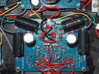
Looking at your PCB I think you would be better off with point-to-point wiring. You will need to buy some (gold plated) valve bases and a metal punch - to punch the correct perfect round holes in the top plate. Then you screw in the valve bases with M3 nuts and bolts, together with tag strips to support components.
Point to point is then simply soldering from valve base pins to tag strip pins to follow the schematic we decide on
I'm going to replace the central driver panel on mine for a new one I think - for the new design which will be far easier with point to point.
I think you may have a bad tube socket, rather than a bad tube - have a close look at the socket at each connector - I had a tube not light up the filament because of that. It needed pushing back with a small screwdriver..
If you are thinking of a new box, a flat metal top on a wooden base is popular, with the existing front and back perhaps? I would think if you dismantled your box you could repair it well, with some wood and a hammer. Which bit of your case is damaged - is it just the top being bent?
I bought a phono amp from Hong Kong that needed a new front panel, the replacement bits did turn up eventually but took _ages_ to arrive - perhaps they use a slower postage for repair bits?
Looking at your PCB I think you would be better off with point-to-point wiring. You will need to buy some (gold plated) valve bases and a metal punch - to punch the correct perfect round holes in the top plate. Then you screw in the valve bases with M3 nuts and bolts, together with tag strips to support components.
Point to point is then simply soldering from valve base pins to tag strip pins to follow the schematic we decide on
I'm going to replace the central driver panel on mine for a new one I think - for the new design which will be far easier with point to point.
Hi!
You were right the problem was in soket tube.
I will look better and see if I can repair the box, the problem is that not only is the top that is bent but also the sides.
I intend to do later point-to-point wiring, for now I'm just trying to make everything to sound right.
As for the sound I'm with mixed feelings. The first impression was a huge soundstage with a lot of detail, but listening more carefully I think the treble is not completely clean (has a little TSHH TSHH especially metals) and the bass could also be a little tighter.
But then there are some recordings that sound really good as it is now.
I do not know if changing tubes will improve the sound or is there something else I can do.
Thanks again for your help
Hi!
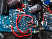
I made some changes to the layout, it seems to me that the sound improved slightly, but I still have problems with the treble.
I've also read some articles on the grid resistor and they recommend values between 1.5K and 5.6K, in post 114 you also say that the the value of grid resistor is 3K.
Cheking my grid resistor I found that the value is 1k, I think this is the problem.
Cheers
Attachments
Hi,
I'm not sure the grid stoppers value has much audible effect - they just work with the grid/miller capacitance to form an RC filter for RF.
Not sure why your treble is not up to par - have you tried it on some older CDs? - modern CD's treble is dreadful anyway. Try the FM radio too - that;s usually cleaner.
The floppy bass is caused by only using about 2dB feedback in the circuit - I suspect the nice soundstage is caused by the same thing, we just need to keep the multistage feedback low but tighten up the the drive to the OPT (output transformer).
The feedback that is there will only affect the midrange - gain at treble and bass will be too low to feedback I think. Currently the feedback works on 4 stages - the driver, the coupling capacitor, the output tube, the transformer. I want to cut the transformer out of that and just use lower drive impedance - formed by using a lot of feedback on a pentode.
I thought of using the negative Vbias for the output tubes as a supply rail - we get -70V biasing our tubes so the supply must be even lower - maybe -80V even. This allows at least one gain stage to be DC coupled - although there is sort of the PSU coupling I guess.
What is TSHH?
Hi!
I think that the 1K grid stoppers resistores on the 6N3p were not enough to prevent oscillation or distortion.
I've replaced them with some 5.6K resitores, I think that the sound has changed and that I no longer have the treble problem... but is too late to to increase the volume and make sure it is ok.
As for TSHH was a weak attempt to describe the sound of cymbals, I think they should be brighter and cleaner.
I think that the 1K grid stoppers resistores on the 6N3p were not enough to prevent oscillation or distortion.
I've replaced them with some 5.6K resitores, I think that the sound has changed and that I no longer have the treble problem... but is too late to to increase the volume and make sure it is ok.
As for TSHH was a weak attempt to describe the sound of cymbals
, I think they should be brighter and cleaner.Ah that would explain it - perhaps your 6N3p stage was ringing. I'm pretty sure mine are all 3k. My tubes are 6N3p-EV by the way.
This is the thread I'm scouting for design ideas in:
GU50 SE ideas
For the next mod, it should be a big step up in sound quality. You may wish to pick up a pair of 6n6p tubes - or if you have a large input signal you could skip the input stage and just use and some 6n2p tubes in SRPP.
I found a free signal generator for my iPod Touch now, so I can use my 'scope to try some full power waveforms (triangle wave) to see how linear it all works out at. I just need to find some dummy loads now
We also need about 250V in VR tubes - we may end up with 2 or 3 of those!
What do you think - any ideas for the next mod?
Hello Globulator,
I've been trying with various values for grid stoppers for the 6n3p resistores but without good results.
I decided to go back to try again 6N6p, put back again the original connections on the socket and the 1k resistor on the cathode.
I like more the sound now, the treble seems more well behaved, but I think I lost some separation between instruments, and detail.
Perhaps 6n6p the is right tube for this amp, but I think we can improve the sound. Any Ideas? perhaps a different value for the 6n6p cathode resistores? or completely remove the feedback?
Cheers,
People say the 6n6p sounds good without bias changes. My next mod takes a bit of power but should be good I think. 6n6p in SRPP with 6N3 driving it, feedback from GU50 to 6n6p only. I think you need to run the 6n6p with more current for it to sound better - 15mA is the sweet spot.
This should linearise the whole amp and drive the OPT far better, much better treble, bass and dynamics.
The only downside is you need a 250V 5mA Zener or an OB2 + OA2 VR tubes with 7 pin sockets. Oh yes and a new silver top plate and some new resistors!
Power consumption is 6W per SRPP + 3W per 6n3, giving 18W used up in the driver stage. This is the main downside as I see it, the problem is getting tubes at 200V plate voltage into a linear region so we can use them.
The alternate is to use an input pentode (only - pentode + GU50) and wire up the set in Schade feedback. This would be power efficient and sound pretty good - may not a better sound in theory but maybe in practice as the PSU would be having an easier time.. Not sure how to linearise the input pentode though, or which one to use - I only have bags of 6AU6s lying about!
Not sure how to linearise the input pentode though, or which one to use - I only have bags of 6AU6s lying about!
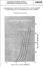
6J51P, 6J52P, 6J53P. Last and best pentodes of color TV era.
Hi All,
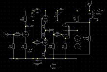
I'm just playing around with a new SRPP driven design for this - please see the attached picture.
The tube lineup is 6N3p, 6N6p, GU50.
The idea is to run the 6N3p at around 4mA, the 6N6p at 8mA and the GU50 at 55mA.
The feedback goes around two stages - no idea of levels, I hope to avoid a capacitor there too but it depends upon how it all works out. I'm aiming for about 9dB of feedback there, or at least between 6 and 9 to give a low impedance to the OPT.
G2 of the GU50 is driven from gas discharge at 5mA giving 150 + 108V
I did have a look at the 6N2p for the driver - but could not see how to get into the best bits of the curve with B+ at 430V.
The rail voltages go 430, 400, 350 approx down the line.
Attachments
How's your russian?
Native.
What are the basic differences between the 51, 52 and 53?
Curves are different.
6J51P:
6J53P:
6J52P has even higher transconductance.
Last edited:
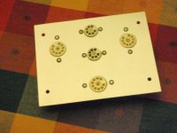
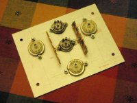
Started on my new driver board now.
The little plate in the middle has now been replicated in anodized alloy (from the cover of the HV section in a Tektronix 545b scope actually - are there no limits to this scope?) and I've used the neat Qmax punches to make some nice holes.
I may have to nibble the chassis a little to fit as the chassis hole is a lot narrower than the plate for some reason.
So the plan is for one input tube (dual triode) and two output tubes - allowing for playing with SRPP, Aikido, and of course strapped pentodes.
I think my last thought was a 6N2p input tube and two 6J51p driver pentodes. The little 7 pin sockets are for the OA2/OB2 gas VR tubes, giving just over 250V regulated to the GU50 screens to run them in pentode mode. Actually these came from the Tek' too..
So this board allows me now to develop the ideas in my post above and chop and change a bit as I have one tube per side on the driver.
More info as time allows, I have to bolt it in and wire up the filaments first with twisted pair, then see about operating points etc. I suspect I need more tagstrip too - maybe I'll hang a couple from the bolts that hold the plate in too.
Attachments
- Status
- This old topic is closed. If you want to reopen this topic, contact a moderator using the "Report Post" button.
- Home
- Amplifiers
- Tubes / Valves
- Trying to make sense of the Sweet Peach