So, please allow me a simple question
I suppose none of you will never build it, but others may
What would you want to happen here, further on, about the Krill ?
just warn that there is a technical innacuracy in the description
of a circuit that claims something wrong...
the point is that claiming krill circuit is non switching is untrue..
Hi wahab
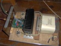
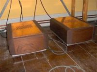
Its "ot", I just like to show you my amps
Yes, they are 40watt AB amps, and very complicated curcuit, 4layer smd etc(Mirand, not mine)
But they sound as sweet as any I have ever heard
And funny thing, they do 2ohm easily, with just a single pair output devices, no sweat
Its "ot", I just like to show you my amps
Yes, they are 40watt AB amps, and very complicated curcuit, 4layer smd etc(Mirand, not mine)
But they sound as sweet as any I have ever heard
And funny thing, they do 2ohm easily, with just a single pair output devices, no sweat
Attachments
Last edited:
I suppose none of you will never build it, but others may
What would you want to happen here, further on, about the Krill ?
Wrong guess.
Nothing, just let it die. Any attempt to resurrect it will surface again the (objective) truth about.
Hi wahab
Its "ot", I just like to show you my amps
Yes, they are 40watt AB amps, and very complicated curcuit, 4layer smd etc(Mirand, not mine)
But they sound as sweet as any I have ever heard
And funny thing, they do 2ohm easily, with just a single pair output devices, no sweat
hi, i love the transformer and heatspreader !!
on the amp , i can t comment , at this distance, not easy
to have an idea , would like to know the topology, though..
is is casing closed in the right?.wood made..it make the thing
look so authentic...great thing you have, tinitus, litteraly..
all da best,
wahab
Wrong guess.
Nothing, just let it die.
Thanks Wahab, I will see what I can do, I will get back to that later
syn08, I dont understand how you can even suggest that, not on the ground of whether its switching or not
Those who have already built it have found no problems with stability etc
Whether it sounds good or not, thats a quite different matter
But its not fore me or you to decide whether Krill have a right to be here or not
But how about we call it a "soft switching" AB amp
What do you think, would that be ok ?
Last edited:
hi, i love the transformer and heatspreader !!
on the amp , i can t comment , at this distance, not easy
to have an idea , would like to know the topology, though..
is is casing closed in the right?.wood made..it make the thing
look so authentic...great thing you have, tinitus, litteraly..
all da best,
wahab
Wahab, here is one thread about Mirand, it's a design by a guy on this forum called sonnya, it's quite impressive in terms of complexity and figures.
http://www.diyaudio.com/forums/solid-state/139439-mirand-a1.html
If you search on sonnya posts/threads you will find more.
About the Krill,
I have been looking at it from the side view so far and what came to my mind from the very beginning is one can use diodes at the inputs of the driver/OP which will also prevent the base charge to be sucked out, the OP stage can only be pulled on through the diode but not off.
Actually a circuit that is supposed to work according to the non-switching off scheme should not show any significant rise in cross conduction current by rise of working frequency, eg. that is there is an intelligence designed into the circuit to keep the cross conduction fairly constant within its working frequency which in this case is the audio band and for different loads (hence higher load means more base charge), can this circuit show such a consistency say from 20 Hz to 20 kHz and, different and reactive loads??
Cheers Michael
Last edited:
I have been looking at it from the side view so far and what came to my mind from the very beginning is one can use diodes at the inputs of the driver/OP which will also prevent the base charge to be sucked out, the OP stage can only be pulled on through the diode but not off.
Actually a circuit that is supposed to work according to the non-switching off scheme should not show any significant rise in cross conduction current by rise of working frequency, eg. that is there is an intelligence designed into the circuit to keep the cross conduction fairly constant within its working frequency which in this case is the audio band and for different loads (hence higher load means more base charge), can this circuit show such a consistency say from 20 Hz to 20 kHz and, different and reactive loads??
thank you for the link, michel;
putting diodes will change nothing, as it will have the same effects as
removing the driver emitter biaising resistances...
the problem is the transfer function is broken as long as the
stored charge is not removed,and it will only mess the amp ability to
control the signal through the negative feedback, as the output devices
don t behave accordingly to the amps tries to correct the non linearity..
adding a variable vbe control to make the crossconduction current constant
is not that easy, and it bring in fact more harm than good, because this will
decrease the global transfer function linearity, thus the amp must rely on
increased NFB ratio...
the better to this day, or at least in my knowledge is to work in deep class AB or even class A...
regards,
wahab
Now would seem to be the time to build and take some measurements
I thought that had already happened?
I thought that had already happened?
It has happened already, but it was done by me years ago. It was also tested by two of the engineers I worked with. Of course, that doesn't prove anything because I'm lying about that also.

Yeah, some members have built it, and seems happy with it, as far as I know
But it my understanding that Steve has used this curcuit previously mainly fore pro work, and that its going through some rework to be used fore music/hifi, or I may have misunderstood
The work it is going through is the evolution that it already went through back when I was building them. I had both pro and home units.
I think one of the members here that has built a pair is planing to do some testing. Many here simply do not have access to the equipment to do the testing.
It would make a good presentation, a triple EF biased at 200mA 10W @1kHz into 8 Ohms and a second (different) triple EF under the same conditions. Plotted on the same graph using the same spectrum analyser. Gosh, who would of thought of it? I could live with without worrying about the sound of each.
... Nothing, just let it die. Any attempt to resurrect it will surface again the (objective) truth about.
Hi syn08,
I would like really like to know how Steve further developed this design, which is what I asked at the beginning of this thread.
I have not found your posts helpful, to date, and I am interested in how Steve further developed this circuit. So, it would probably be better if you stopped posting and allow Steve to discuss how he improved his Krill circuit.
thanks
Hi All,
Isn't a slow turn off (if the transistors never actually turn off (reach 0V)) still a form of non-switching?
If not, perhaps someone (other than syn08 or GK) could tell me the correct interpretation of non-switching?
thanks
I have not found your posts helpful, to date, and I am interested in how Steve further developed this circuit. So, it would probably be better if you stopped posting and allow Steve to discuss how he improved his Krill circuit.
If not, perhaps someone (other than syn08 or GK) could tell me the correct interpretation of non-switching?
I eventually may or may not stop posting, that's certainly my call. And anyway, this has nothing to do with the facts about Krill. And one fact is, Krill has at best (if not worse) the crossover distortion performance of a triple EF.
I would myself be curious of another interpretation of "non-switching", beyond what was already discussed by Scott, Andy, GK, yours truly, and a few other.
Otherwise, as a rule, inconvenient truths are never easy to be found helpful.
KLe,
Most importantly, a non-switching state means device(s) amplifying the full signal wave form.
The goal should be to keep both! devices in conduction in all combinations of input voltage / output current, in a simple and straightforward manner to avoid much damage to the signal and to obtain small inherent time delay. The latter in particular sets the limit on what can be achieved, sometimes you hear people talking about class A sound, that`s however, aiming far too high.
It´s an authentic switching (commutation véritable in French). In this respect, it´s not a matter of speed, rather operating point determining transfer characteristic.Isn't a slow turn off (if the transistors never actually turn off (reach 0V)) still a form of non-switching?
Most importantly, a non-switching state means device(s) amplifying the full signal wave form.
The goal should be to keep both! devices in conduction in all combinations of input voltage / output current, in a simple and straightforward manner to avoid much damage to the signal and to obtain small inherent time delay. The latter in particular sets the limit on what can be achieved, sometimes you hear people talking about class A sound, that`s however, aiming far too high.
... Krill has at best (if not worse) the crossover distortion performance of a triple EF.
Hi syn08,
Perhaps the real benefit (from what I have been reading) of the Krill circuit is the lower bias current (<= 100ma) and perhaps the crossover distortion performance at >10K (especially >20K)?
From what you are saying it sounds like you would prefer to implement a triple EF, which is fine, but Steve has indicated that he has made many improvements to this Krill circuit and even produced 200w and 500w models.
I would love to hear about these improvements (as I indicated in my initial post), hopefully you are interested also.
thanks
... It´s an authentic switching (commutation véritable in French). In this respect, it´s not a matter of speed, rather operating point determining transfer characteristic.
Most importantly, a non-switching state means device(s) amplifying the full signal wave form.
The goal should be to keep both! devices in conduction in all combinations of input voltage / output current, in a simple and straightforward manner to avoid much damage to the signal and to obtain small inherent time delay. The latter in particular sets the limit on what can be achieved, sometimes you hear people talking about class A sound, that`s however, aiming far too high.
Hi Lumba Ogir,
From your explanation I believe we could say that the Krill circuit is non-switching and from syn08's explanation; the crossover distortion performance is at best (if not worse) than a triple EF?
Have I interpreted that correctly?
Thanks
to bring an end to this endless debate about the status of this circuit,
here my contribution :
it has an emitter follower ouput pair, and this configuration
has a crossconduction range of about 10 V .....
the higher the signal, the close to switching (commutation)
it happens that the configuration of the krill has no driver
bias resistor, thus somewhat widening the crossconduction range..
this widening is because of no driver bias resistors, not because of
the krill topology...the mesaures that where displayed where for
many made with a 20 V PP sinewave, for a 60 V PP capable supply,
thus, the input signal was low enough to let remaining some crossconduction,
although it was only in a pair of hundreds uA, it can be hardly qualified as crossconduction..
should have the signal used be higher, let say 40 V PP, the crossconduction
whould have be measured in Na....
thus, the krill is a switching stage...
a real non switching stage would maintain the idle current in the non
conducting pair...
if the quiescent current is let say 100mA, then, when the upper
device stage conduct, the bottom pair must still be biaised with this current,
thus conducting the idle current permanently, no matter at what voltage
the output is brought by the upper device stage, and vice versa in the negative
going of the signal..
the switching is the results of an increase of the conducting junctions Vbe,
as pointed by ultima thule....this would be adressed by a circuit which
compensate the Vbe s , keeping in mind that these latters are output current
dependend...it is do able, but at the expense of other parameters...
it s also pointed that the krill produce the distorsion of a triple emitter follower..
for sure, as it s exactly that...
regards,
wahab
- Status
- This old topic is closed. If you want to reopen this topic, contact a moderator using the "Report Post" button.
- Home
- Amplifiers
- Solid State
- Krill - The Next Generation