Hello,
Just to confirm that it will be difficult to assemble the Katana Dac without the isolator on the Usbbridge SIG board as there are capacitors whose metal body can get in touch with other parts of the dac...
I tried it by myself without success.
Thank you for that, that was my impression. Looking at the images from @TimCurtis in his post #591 it looks like he has extended the stand-offs and lifted the GPIO a little.
I'd be interested in a breakdown of the Ethernet and USB design on the SIG. Looking at the board there are two chips:
USB - Texas Instruments TUSB4041l (4-port USB 2.0 hub)
http://www.ti.com/product/TUSB4041I?jktype=didyoumean
Eth - ASIX AX88179_178a
AX88179 - USB 3.0 to Gigabit Ethernet (GbE,GigE) | ASIX
I'm aware that the Allo enhanced driver for the 88179 bumps the Ethernet speed from 100 Mbps to 330 Mbps but exactly what PCM, DSD (native) and DoP rates are supported over the USB interface ?
-Tim
Hello,
Just to confirm that it will be difficult to assemble the Katana Dac without the isolator on the Usbbridge SIG board as there are capacitors whose metal body can get in touch with other parts of the dac...
I tried it by myself without success.
I will check on Monday
DSD 512 tested , DSD 1024 possible theoretically
PCM 384Khz tested , 768 possible theoretically
I assume you mean DSD512 bitstream which if I have the numbers correct is:
1 bit, 45.152 Mbps Stereo (equivalent to 705.6 kHz PCM)
PCM 384K would enable:
DSD128 DoP - 24 bit 352.8 kHz, Stereo, 16,934 Mbps
PCM 768K would enable:
DSD256 DoP - 24 bit 705.6 kHz, Stereo, 33.868 Mbps
-Tim
Hello,
Just to confirm that it will be difficult to assemble the Katana Dac without the isolator on the Usbbridge SIG board as there are capacitors whose metal body can get in touch with other parts of the dac...
I tried it by myself without success.
I checked this earlier in the week when planning Katana trials without the Isolator on a USBBridge Sig.
The RPi GPIO header on the USBBSig is about 3mm taller than that on a stock RPi due to it being a surface-mount header instead of through-hole. The pins are about 1.5mm longer. That gives you plenty of leeway to add more spacers to lift the Supercaps on the bottom of the Katana DAC board above the filter caps on the USBBSig.
I suggest first insulating the Supercaps with something like Kapton tape, then selecting additional or longer spacers to provide the needed height. With about 1/2mm of clearance between the Katana DAC board Supercaps and the USBBSig filter caps you'll still have plenty of GPIO pin length in the Katana DAC board sockets.
BUT do be careful on your spacers. There are filter caps very close to the RPi footprint mounting holes on the USBBridge Signature. IF you use metal spacers or washers that are any larger than the mounting hole outline, you risk shorting those and having a bad day for your USBBridge Sig and any attached HAT. When in doubt check for continuity. I use fiber washers here.
Greg in Mississippi
Last edited:
PSA for US Shanti customers. Please double check the voltage setting on the back. Mine came pre-selected as 230V, and I’d been using it like that for several weeks. It still worked, and sounded amazing, though the banks registered 5.06 and 4.98 V. After switching to 115V, the banks both registered ~5.2V!
I’m sure mine is a one-off case, but it doesn’t hurt to double check.
I’m sure mine is a one-off case, but it doesn’t hurt to double check.
Hi cdsgames,
I have 3 little questions about Usbbridge SIG;
-Where do I have to ground it? to the chassis/enclosure? or directly to the ground wire of the IEC connector of my setup?
-In the picture attached, the connectors in green are the 5v DC in?
is that right?
-What are the use of the connectors in red on the pîcture?
thank you
Attachments
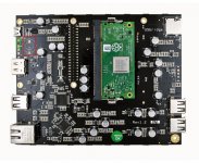
@terry22,
I can help with this...
- Grounding position is the mounting hole on the bottom right in the picture you posted... see the grounding symbol there.
- Green-marked connection points ARE the 5V DC input. You can also feed 5V into the MicroUSB, but the connection points with a flying lead and a good connector should be better. Note that both of these go though a protection diode, though a higher-quality one than on stock RPis. I have not yet tried bypassing it to see if I can hear any difference.
- The connection points in red are for a Supercap, the same .33F/5V unit Allo uses on the Katana boards and the Bosses. There is a place for another on the bottom of the board on the opposite side. I asked Allo about installing them and they said they didn't see any measurable differences with them in or out (as opposed to what they saw on something like the Katana) and that in, you have to wait for the SC to discharge before attempting a reboot.
Greg in Mississippi
@terry22,
I can help with this...
- Grounding position is the mounting hole on the bottom right in the picture you posted... see the grounding symbol there.
- Green-marked connection points ARE the 5V DC input. You can also feed 5V into the MicroUSB, but the connection points with a flying lead and a good connector should be better. Note that both of these go though a protection diode, though a higher-quality one than on stock RPis. I have not yet tried bypassing it to see if I can hear any difference.
- The connection points in red are for a Supercap, the same .33F/5V unit Allo uses on the Katana boards and the Bosses. There is a place for another on the bottom of the board on the opposite side. I asked Allo about installing them and they said they didn't see any measurable differences with them in or out (as opposed to what they saw on something like the Katana) and that in, you have to wait for the SC to discharge before attempting a reboot.
Greg in Mississippi
Hi Greg,
Thank you for your answer.
About grouding, I was more specificaly asking if I have to connect usbbridge ground hole to the chassis or directly to the ground of my AC IEC/plug.
Hi Terry
I recommend connecting PCB earth to chassis and then chassis to AC earth
Thank you!
- Home
- Vendor's Bazaar
- Shanti Dual LPS 5V/3A , 5V/1.5A