Though it would require some delicate modding that would give these discrete DACs an advantage for paralleling or balancing since I think all R2R chips had internal references?"Gain" is only determined by Vref. I don't see any issues sharing a single Vref among several boards.
The PCM1704 does have an invert pin, so maybe its not really a problem unless there is some reason for that invert feature other than balanced output (datasheet does not mention their intended use for the pin)
Last edited:
soekris,
Any Black Friday discounts planned this year?
No
It is fascinating and more than a little ironic that so many people who choose to devote their time to audio measurements are completely lacking of even basic listening abilities.
Cornix cornici oculos non effodiet
What I find interesting with making my speaker measurements is how one loses confidence in their hearing abilities.
You make a change and then you think: it must be verified/vindicated by REW!
Not that i have fallen into this trap so far I can no longer make it back out but I must keep it in mind at all times.
Like the self taught musician who used to be able to sit down with the guitar an come up with all kinds of stuff and as soon as he learns some theory that ability goes away.
Like how writing something down makes it harder to remember it?
So you are essentially saying that for designing a great piece of audio equipment one doesn't necessary need any education, theoretical knowledge, and experimental procedures and equipment. All that is required is a pair of great trained ears and previous experiences of the same kind.
How convenient. Electronics, acoustics, signal processing are for wussy amateurs only, right?
I guess you understand what it is you are attempting to say but I know i cannot figure out anything of use from your comment.
I was just making a comment about the frailties of human perception and how we must remain aware of our limitations.
I can only assume you have thrown caution to the winds when it comes to limitations and decided to carry on sans souci, or something very similar to that ...
I was just making a comment about the frailties of human perception and how we must remain aware of our limitations.
I can only assume you have thrown caution to the winds when it comes to limitations and decided to carry on sans souci, or something very similar to that ...
I guess you understand what it is you are attempting to say but I know i cannot figure out anything of use from your comment.
I'm afraid we have more comprehension than hearing ability differences.
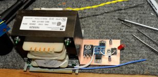
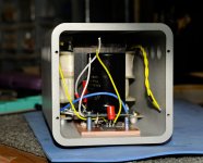
Finally got supplies assembled.
Since they are not regulated I thought it best to be sure i was getting correct voltages before making final assembly - I thought it would be best to text the digital supply and the analog supplies separately. The original board could be powered on separately. Is this still the case?
I connect the digital supply and nothing happens. I figure there is an LED like there used to be to signal and it is obvious from my voltage meter that nothing is happening. I started with a small value bleeder to be sure I did not go over voltage. Which I wouod subsequently make larger until I get the correct voltage.
I measure resistance between the digital power input and pins #3 & 5 for 5 volts out on the adjacent header and there is infinite resistance. I have assumed it would be zero. Is this correct?
I did remove the small choke at the input and have made sure there is continuity between the input pin and the inside pad where the choke used to be. I used a small piece of copper foil to bridge.
Do you think I disturbed something else when I removed the choke?
Does the analog supply have to be on? Is there a relay for the digital supply that is powered by the analog supply?
Finally got supplies assembled.
Since they are not regulated I thought it best to be sure i was getting correct voltages before making final assembly - I thought it would be best to text the digital supply and the analog supplies separately. The original board could be powered on separately. Is this still the case?
I connect the digital supply and nothing happens. I figure there is an LED like there used to be to signal and it is obvious from my voltage meter that nothing is happening. I started with a small value bleeder to be sure I did not go over voltage. Which I wouod subsequently make larger until I get the correct voltage.
I measure resistance between the digital power input and pins #3 & 5 for 5 volts out on the adjacent header and there is infinite resistance. I have assumed it would be zero. Is this correct?
I did remove the small choke at the input and have made sure there is continuity between the input pin and the inside pad where the choke used to be. I used a small piece of copper foil to bridge.
Do you think I disturbed something else when I removed the choke?
Does the analog supply have to be on? Is there a relay for the digital supply that is powered by the analog supply?
There is the green status LED on the dam190x1, just like on the dam1021, and with the same function. Digital Power should be enough to get life in the LED....
Why do you want to remove that inductor, you should first get the board going as standard before starting doing modifications....
Nothing will happen unless the Digital Power is within specs, and that's hard to do with an unregulated supply....
What do you mean by "adjacent header", please be more specific, they're all marked....
J4 is the header.
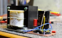
Having read the breathless praise of the IFi switcher I have ordered one of those for the digital supply.
If it really only has 1uV of noise - I know i could never approach that.
I removed the choke when planning on using the SALAS shunt reg and got the feeling from Salas that his reg would probably be happier without it.
I wonder if the switcher would, also, prefer it gone?
It is that insatiable desire to DO something to it. I may replace them in time.
I had to try it to find out - but i figure I am better off using the switcher instead of my mountain of chokes and capacitors for the digital supply. Should have said "looks like I have no other choice. The batteries worked (before) since they are basically regulated internally and had immense current delivery capability. My linear supply was heroic - low resistance chokes - but I am sure your instinct is correct - not up to the task for the current. (choke input - 100mH/.8R with a second stage of 160mH/3.9R)
AS ALWAYS, thanks very much for your guidance and patience.
Take care,
I do have the line of finished DACs.... The dam1921/dam1941 is a DIY/OEM product, anybody can design cases and accessory boards, the docs will be there, and I might work with case manufacturers to make cases....
Dear Soeren,
...are you still planning to do this?
Regards,
Mickie
There had been playful comments made about mono 1941s and TNT suggested using two boards for this.
I am thinking about giving this a try since the rest of my system is dual mono.
But how would one implement this? Can you split an USB connection and have it feed both boards? Same question for I2S - would it be as simple as running the wires to both boards?
I am thinking about giving this a try since the rest of my system is dual mono.
But how would one implement this? Can you split an USB connection and have it feed both boards? Same question for I2S - would it be as simple as running the wires to both boards?
")
No, it is not!
That is why I asked my question.
Having respect for TNT's knowledge while also realizing he has a fine, sharp sense of humor (along with the best tag line in all of audio) I wondered how this could be done in either I2S or USB.
One wonders what would happen if either of these signals were split and sent to two separate DACs? Would the host go crazy or would the DACs? Or could a miracle happen and it simply WORK?
But then I really expected YOU to know! I thought you had tried everything, Mr. Daniel!
After blowing up my SDTrans after forgetting to disconnect it during a power supply experiment I am back to the computer and USB.
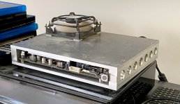
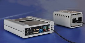
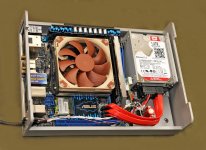
Did you carefully select a motherboard or just using something?
I still look for the lowest power consumption I can find. Thinking about getting an embedded ASROCK with soldered in CPU - 10 watts power consumption. ASROCK always has very flexible and extensive BIOS.
My player of choice is WTFPLAY. What are you using these days?
That is why I asked my question.
Having respect for TNT's knowledge while also realizing he has a fine, sharp sense of humor (along with the best tag line in all of audio) I wondered how this could be done in either I2S or USB.
One wonders what would happen if either of these signals were split and sent to two separate DACs? Would the host go crazy or would the DACs? Or could a miracle happen and it simply WORK?
But then I really expected YOU to know! I thought you had tried everything, Mr. Daniel!
After blowing up my SDTrans after forgetting to disconnect it during a power supply experiment I am back to the computer and USB.
Did you carefully select a motherboard or just using something?
I still look for the lowest power consumption I can find. Thinking about getting an embedded ASROCK with soldered in CPU - 10 watts power consumption. ASROCK always has very flexible and extensive BIOS.
My player of choice is WTFPLAY. What are you using these days?
Did you carefully select a motherboard or just using something?
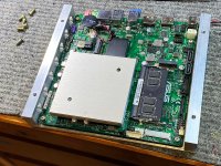
That's an interesting question, everybody talks here about the DAC not mentioning source equipment, which can be quite important..
Presently I'm using a simple ASUS board with Pentium chip, all powered from passive linear supply. In my initial tests it sounded better than more advanced PCs I've built earlier. Source material comes from Synology NAS.
Attachments
I came to computer transport from cicis's CPLAY and still think he was on the right track.
All of these fellows with absurd upsampling and the noise this generates - I figure they get that tingle up their leg just thinking about how much nonsense is being processed with little regard to what it sounds like. Of course, they could like the sound of what I call the digital sparklies in the background?
I think WTFPLAY is about as good as it can get though I say that without having heard any of the WINDOWS based players in years. It is a LINUX player that loads up from LiveCD in a minute if it takes that long. Aesthetically it appeals to me in every way - both sonically and architecturally.
If Mies van der Rohe made a music player ... nothing there that doesn't need to be there. As graceful as the SEAGRAM BUILDING.
Small enough to fit on your memory so a fresh install every time you use it. I am using 2 gB of memory. It would work with only 1 gB but I had to be careful about putting too many files on the playlist.
SO, what player are you using?
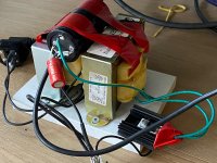
Last time I was serious about computer audio I used a simple board with the lowest power Intel desktop CPU available.
My supply was linear and based upon the A123 batteries and a big blue OPTIMA marine battery for the CPU rail.
It was a giant pain in the rear that took up a whole corner of my listening room.
Never doing that again.
There are so many switchers on the MB why obsess over a few more? I will be using the HDPLEX version of the Picopsu. I do worry MBs need bursts of power even an A123 or OPTIMA battery cannot supply. I know YOU are not a fan of battery power supplies! And I am not either, now. I finally got what you were warning about all those years ago. Dynamically challenged unless absurdly over specified. And there are not many batteries available with more 12 volts power than the OPTIMA blue.
Have you tried those IFI wallwarts? They seem to sound very good. More properly they are hard to hear.
Instead of trying to get to the incoming power for the XMOS I have spliced one of these IFI supplies into the USB cable.
Second question: do you think it would be possible to use the same USB output to drive two 1941 boards? Sorry to be repetitive ...
Take care,
There had been playful comments made about mono 1941s and TNT suggested using two boards for this.
I am thinking about giving this a try since the rest of my system is dual mono.
But how would one implement this? Can you split an USB connection and have it feed both boards? Same question for I2S - would it be as simple as running the wires to both boards?
The dam19x1 is designed as a single integrated digital package, not to be connected as multiple boards, it's up to you if you want to try to but I see plenty of roadblocks....
But why not use multiple dam1021's or dam1121's, they can run as multiple boards ?
- Home
- Vendor's Bazaar
- dam1941 - Next Gen Discrete R-2R Sign Magnitude 24 bit 384 Khz DAC module