Depends on what output voltage you desire. The Vf of VSB3200S-M3/73 is somewhat high compared to other Schotky 3A diodes.
Non modular means designing single board stuff instead of n boards connected with afwul soldered wiring. I am really annoyed by excess and unnecessary wiring and certainly when it is mentioned that the boards can be reused (who does ?). Just like Stammheim I design PSU's that have everything on the PCB maybe except the transformer when its too large and heavy. PSU boards without rectifier and filter caps are a no no for instance. Preamp boards should have volume control and input relais all on one board. It is a principle in life
Non modular means designing single board stuff instead of n boards connected with afwul soldered wiring. I am really annoyed by excess and unnecessary wiring and certainly when it is mentioned that the boards can be reused (who does ?). Just like Stammheim I design PSU's that have everything on the PCB maybe except the transformer when its too large and heavy. PSU boards without rectifier and filter caps are a no no for instance. Preamp boards should have volume control and input relais all on one board. It is a principle in life
Last edited:
Non modular means designing single board stuff instead of n boards connected with afwul soldered wiring. I am really annoyed by excess and unnecessary wiring... It is a principle in life
I see, sounds good. Thank you.
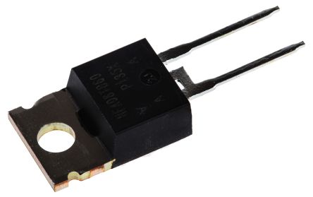
So I found this this rectifier that caught my eyes due to the 1,7v Vf and the description of it on the data sheet.
Vishay VS-HFA08TB60-N3 Switching Diode, 600V 8A, 2-Pin TO-220AC
VS-HFA08TB60-N3 | Vishay VS-HFA08TB60-N3 Switching Diode, 600V 8A, 2-Pin TO-220AC | Vishay
https://docs-emea.rs-online.com/webdocs/0791/0900766b8079107f.pdf
Does this one make sense using a 12VAC transformer powering a 12VDC/1.5A Brooklyn DAC with HC-HPULNs in series? If it does I will change all four rectifiers on the first HC-HPULN to these Vishay Schottys. The second HC-HPULN will have its supplied rectifier diods.
Last edited:
LQA10T300 Power Integrations | Mouser United Kingdom
These really take some beating, super fast and incredibly soft recovery. In most cases they're so good you don't even need an RC-R snubber.
These really take some beating, super fast and incredibly soft recovery. In most cases they're so good you don't even need an RC-R snubber.
Does this one make sense using a 12VAC transformer powering a 12VDC/1.5A Brooklyn DAC with HC-HPULNs in series?
Doubtful. 12VAC x 1,414= 17V - 0,4 = 16,6 VDC. There will of course be ripple. Ripple voltage will be 1,6V at 1,5A... 16,6 - 1,6 = 15V. You can set that one for 13,5V. You will loose 0,4V in the rectifiers of the second series modules so you have 13,1V left for the second regulator that has to regulate to 12V.
I don't think second modules in series WITH rectifier diodes is a wise decision as things can get tight. Best is to design worst case in both directions.
* Or study the schematic of the device and determine if it can be fed a lower DC voltage. Often a certain headroom is involved and does the device have internal regulators that drop down that 12V further. It can be rewarding to check how low you can go and optimize the whole chain. I don't know that device but I have seen situations with mediocre regs, it won't be optimal to use the best regs in the world in such cases. I just checked that particular device and see it has its own SMPS and a 12V DC input. Maybe internal regs are of less quality and changing the situation to LT3045 and adapt the PSU supplying the new situation is a good idea. It would maybe create a series situation and no need for a triple series situation.
Last edited:
Also short wiring is beneficial so a case with approx. the same dimensions for the new PSU is technically a good solution. It could also accomodate possible extra separate regulator boards for the various circuits in that DAC and the new transformer. It would also mean omitting the horrendous barrel connector which is a curse in good audio. Getting rid of the SMPS can make room for better hardware too. If the lowest drop is chosen for a new internal 12V regulator heat possibly can be kept within safe limits. With for instance a drop of 1V the generated heat will only be 1,5W.
Just some ideas.... and way off topic...
edit: in pots #205 ripple voltage is Vpp....
Just some ideas.... and way off topic...
edit: in pots #205 ripple voltage is Vpp....
Last edited:
Thanks a lot for your input @jean-paul! Much appreciated!
I actually did´nt know that ripple voltage affected the Vf, so that was very good to know. 1,6Vf (+0,8Vf of the dual HC-HPULN) is actually as close to optimal as possible with my 12VAC-12VDC LPSU. Anyway, hopefully it will line up IRL. I will go with the original rectifiers and ofcourse measure it carefully. I will post some pictures here when I have put it all together.
Thanks for your thoughts about the Brooklyn DAC as well. These are things that I have considered as well, but the LPSU I am doing right know is both a mission to make the optimal LPSU according to me, to aducate myself and to gain confidence to DIY the Brooklyn DAC.
If my two LPSUs turn out as great as I am hoping for I have a long term mind-project as well that includes an all-in-one box sulution to power my intire setup. This box will contain a balanced *floating* isolation transformer, six torodial transformers (one for each series LT3045) and twelve 1.5A LT3045s. Anyway, perhaps a nice project for my retirement days?
LQA10T300 Power Integrations | Mouser United Kingdom
These really take some beating, super fast and incredibly soft recovery. In most cases they're so good you don't even need an RC-R snubber.
Interesting thanks! I have bookmarked this one for future references!
When the ripple voltage causes input voltage to be under the minimum input voltage of the regulator in question it wont regulate anymore. Ripple voltage depends on load current, filter cap value and mains frequency.
So one designs with a safe margin and calculates both ways so with a minimal mains voltage and with a maximum mains voltage. Secondly one calculates with a minimal load and with a maxmum load. The whole point with ULDO regs is to design and calculate with as least loss in heat possible but you still want a safe margin for reliable operation. You will see that this can be quite difficult with low voltages and standard transformer values.
You will also see that it is even harder when you use a single transformer for various regs with different voltages. You can imagine a certain sweet spot in voltage drop only makes matters more complicated, even more so when the transformer is a given factor. That is why looking at the whole chain instead of just one building block is needed.
In case of this Brooklyn DAC I would either replace the SMPS for a way better one (if really necessary, measuring and listening will tell) or use A Stammheim single PSU and build it in the device. Then it can be fed AC or DC depending on how far you want to go. Most difficult and involving modification of the DAC itself is an external box with the whole shebang in it.
Just read your post and you mention the worst of transformers: toroids. Please educate yourself in what choice there is and what to choose if you want PSU's to be quiet and excellent.
Last edited:
When the ripple voltage causes input voltage to be under the minimum input voltage of the regulator in question it wont regulate anymore. Ripple voltage depends on load current, filter cap value and mains frequency.
So one designs with a safe margin and calculates both ways so with a minimal mains voltage and with a maximum mains voltage. Secondly one calculates with a minimal load and with a maxmum load. The whole point with ULDO regs is to design and calculate with as least loss in heat possible but you still want a safe margin for reliable operation. You will see that this can be quite difficult with low voltages and standard transformer values.
You will also see that it is even harder when you use a single trahnsformer for various voltages.
Thanks for your advices!
I will keep them in mind. I hope to receive the 230-12VAC balanced isolated ps by next week. It will be interesting to see how the voltages lines-up IRL. I could always remove the recifiers on the second HC-HPULN to gain +0,4 V if needed (and if it helps). The all-in one mind-project will need some serious thinking before I even start. Heat, size, voltage requirements, load, confidence & total cost are all make-or-brake factors if this one will be realized or not.
To the ripple, better the expensive Mundorf MLGO 125ºC electrolytics.
The 22,000uf 63V and 33,000uF 40V are too tall to my DC Blocker. I bought the 47,000uF 25V. I LOVE them. Expensive but very good.
The 22,000uf 63V and 33,000uF 40V are too tall to my DC Blocker. I bought the 47,000uF 25V. I LOVE them. Expensive but very good.
You could use a !:! mains voltage isolation transformer. I use a medical version with good results. It creates an isolated mini-grid for audio devices.
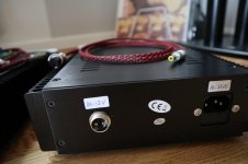
I already do, but a balanced one (plus a DC blocker trap filter in front of it) that looks like this internally.
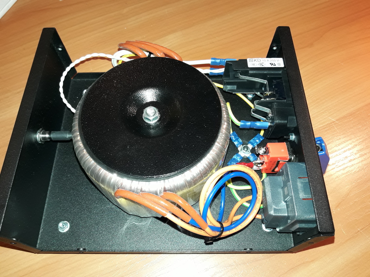
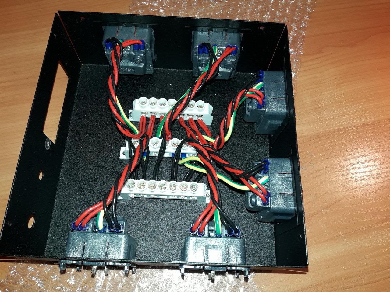
It is connected to this star-earthed power distributor.
This balanced *floating* isolation transformer together with the LT3045s in series is actually the biggest reason why I want to build my LPSUs.
As you can see on the picture there is a switch on the balanced isolation transformer where I can choose to *float* or *ground*. No contest in my setup. *Floating* sounds by far the best.
Interesting Maty!
Is the Mundorf´s a drop-in repacement into ALT´s DC Blocker trap filter? PS. Maybe this is starting to be too much off topic though? Maybe you send the answer to me on pm?
Yes, in the DC Blocker prototype that Aleksandar made for me, with my requirements (are standard in the new cases). The following cases have the finished wires, as they are not a prototype.
My others DC Blockers have the BIG EPCOS 18,000uF 105ºC but it will take months until the factory produces them again.
If I had to order another, yes or yes with those expensive Mundorf.
These are the ones I would use for the capacitor bank (4+4=8 caps) of the DIY class A ALPHA 20 amplifier if my boxes were more sensitive. A ruin but... with eyes closes. And in the DIY Aksa's Lender preamp too.
Aksa Lender P-mos Hybrid Aleph (ALPHA) Amplifier
AKSA's Lender Preamp with 40Vpp Output
Ouch, next time with PM. Sorry.
Last edited:
This thread is going from left to right and back in microseconds. Ripple voltage is the voltage after rectification of AC voltages. It depends on mains frequency, filter cap size and load current.
Why now DC blocking of mains voltage is involved ?! Ripple voltage in AC mains voltage ? I suggest Stammheim to ask the mods to clean up the thread as it is almost exclusively off topic now.
* Please be aware that using toroids is not a solution but a choice for more problems.
Why now DC blocking of mains voltage is involved ?! Ripple voltage in AC mains voltage ? I suggest Stammheim to ask the mods to clean up the thread as it is almost exclusively off topic now.
* Please be aware that using toroids is not a solution but a choice for more problems.
Last edited:
(Gophert>HC-HPULN>HC-HPULN)
Hi
Are this HC-HPULN with the rectifier in the input or without
They aren't needed, because the Gophert Output is DC?
LG
Thomas
Hi
Are this HC-HPULN with the rectifier in the input or without
They aren't needed, because the Gophert Output is DC?
LG
Thomas
No, the rectifiers is not needed with Gophert, but I want to keep mine versitail to be able to compare Gophert to the 12VAC balanced isolated ps that actually arrived on my doorstep today!
Attachments
Last edited:
- Home
- Vendor's Bazaar
- FS: „Ultra Low Noise“ Power Supply, LT3045 based PCB’s