With your current configuration having .26V differential, ripple rejection is as low 10dB. At that rate, it would take 8 series LT3045 for equivalent ripple rejection as one LT3045 at 2V differential (around 80dB).
Here's an example of a fully optimized configuration...
Transformer 24VAC out -> S12 18VDC out -> HC-HPULN 15VDC out -> HC-HPULN 12VDC out
However, to reduce heat under higher current, I'm going with just 1.5V differential between HC-HPULN. Really anything over 1V should be getting the majority of use out of the LT3045.
Your required transformer output voltage depends on...
1) Whether you're using a PS between the transformer and LT3045
2) How many series LT3045
3) Voltage differential after each LT3045
4) Final output voltage
Last edited:
I'm finding we should be referring to the σ11 (sigma 11) rather than S12, because the S12 and S11 variants are a copy of the σ11 DIY project created by AMB Laboratories.
LittleScarabee, I'd add that configuring voltages with transformer/bridge rectification is confusing to me as well. Even after reading up on it. I just left it up to the seller to configure it for me.
LittleScarabee, I'd add that configuring voltages with transformer/bridge rectification is confusing to me as well. Even after reading up on it. I just left it up to the seller to configure it for me.
I'm finding we should be referring to the σ11 (sigma 11) rather than S12, because the S12 and S11 variants are a copy of the σ11 DIY project created by AMB Laboratories.
LittleScarabee, I'd add that configuring voltages with transformer/bridge rectification is confusing to me as well. Even after reading up on it. I just left it up to the seller to configure it for me.
Regarding the Sigma 11 (S12) here is the information I got from the seller:
The transformer used in this PSU is calculated as follows: Transformer AC voltage * 1.4 - Actual output DC voltage = 10-16V (Normal differential pressure).
Sigma 11 needs a minimum of 10v drop-down.
Okay this clears up a lot. The transformer is rated at RMS voltage, and you use the peak voltage (RMS x square root of two) of the transformer's AC signal for the rectified voltage.
So when wiring directly from rectifier to HC-HPULN without Sigma 11, you'd actually use a much less RMS voltage transformer than with Sigma 11, because the Sigma 11 has greater minimum drop down voltage.
Very good to know!
So when wiring directly from rectifier to HC-HPULN without Sigma 11, you'd actually use a much less RMS voltage transformer than with Sigma 11, because the Sigma 11 has greater minimum drop down voltage.
Very good to know!
Okay this clears up a lot. The transformer is rated at RMS voltage, and you use the peak voltage (RMS x square root of two) of the transformer's AC signal for the rectified voltage.
So when wiring directly from rectifier to HC-HPULN without Sigma 11, you'd actually use a much less RMS voltage transformer than with Sigma 11, because the Sigma 11 has greater minimum drop down voltage.
Very good to know!
Yes, that´s why my 15VAC balanced ps was'nt enough for Sigma 11>dual HC-HPULNs with 12VDC output to Brooklyn DAC. It was just a 7,5v drop-down with Sigma 11 which is not enough. To use this combo a 18VAC balanced PS in needed.
Anyway, I am now heading for a 12VAC balanced PS>dual HC-HPULNs (2.3v drop down between the boards)>Brooklyn DAC (12V) and 15VAC balanced ps>Sigma 11 (9v output)>LT3045 1A (8v)>HPULN 3A (7v)>ISO Regen (7v)
Last edited:
The only thing that comes to mind is to use a Kemet A750 series aluminum Polymer cap at the output of the S12 (and possibly also at the input of the first HC-HPULN) which have improved things a lot in my setup lately. Otherwise just mind the cables. I personally use starquad AC & DC cables. Adding a JSSG around the starquad cables will protect them against airborn RFI/EMI. JSSG is a shield mesh tube around the cable that have a single drain wire (~28awg) soldered to each end of the tube acting as a Faraday cage for the cables. A great little tweak by John Swenson.
Ghent Audio knows how to make them to a fair price.
I will be very interested to know how your LPSU with S12 and HC-HPULNs will turn out. I will surely report back here with my own findings of my two versions as well! 😎
Micael
Thanks for the recommendations.. What uF rating for the Kemet A750 capcitors?
According to AMD (developer of the Sigma 11 design), minimum voltage drop seems to be less than 10V (see here).
Here's an outline of my plan as it stands. To prolong MTBF, I configured the cooling a little more than needed. I also make direct wire connections through cord grips, rather than using connectors and terminals. This eliminates all the fuss about which connectors are best and whether it makes any difference. Let me know if anything needs adjusted..
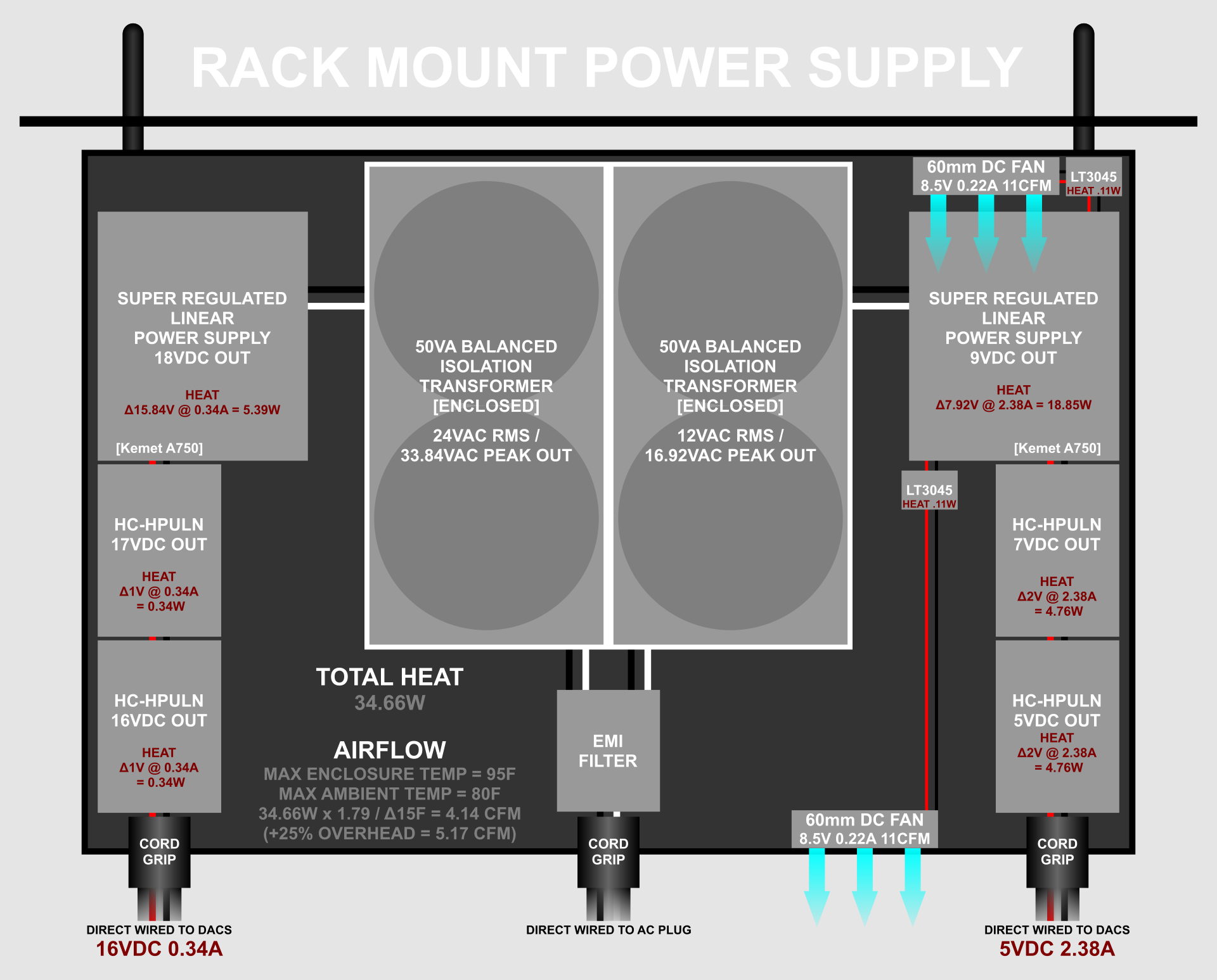
I'm awaiting the components and the rack mount enclosure. I'll post photos when complete.
BTW is everyone here named Michael? I'm Mike and I've spoken to two others here.
Thanks for the recommendations.. What uF rating for the Kemet A750 capcitors?
According to AMD (developer of the Sigma 11 design), minimum voltage drop seems to be less than 10V (see here).
Here's an outline of my plan as it stands. To prolong MTBF, I configured the cooling a little more than needed. I also make direct wire connections through cord grips, rather than using connectors and terminals. This eliminates all the fuss about which connectors are best and whether it makes any difference. Let me know if anything needs adjusted..
I'm awaiting the components and the rack mount enclosure. I'll post photos when complete.
BTW is everyone here named Michael? I'm Mike and I've spoken to two others here.
I thought so as well, but the seller did´nt recommend lower than 10v drop down. That´s why I changed my order on the (S12) Sigma 11.
I use the same voltage and uF rating as used on the HC-HPULN, ie 25v/560uF.
Awesome stuff! Very impressive well thought of design I must say. Not much more to want except maybe to loose the DC fans, but that might be a tricky one to overcome. You can actually use Kemet A750 on both input and output of the LT3045 voltage regs powering the DC fans. IME single LT3045 improve with them on both input and output. Since they are a very small investment it is surely worth a try if you ask me! 😉 I would love to see some pictures during the biuld! 🙂
I have also noticed that Michael/Mike and also Alex is a very common name around audiophile forums! 😀
Last edited:
Strange, the same seller recommended 7.92V drop down on my 9V line, which seems to be in line with AMB's post.
The fans were also my concern. Usually I use a temp/fan speed controller, but I wanted to eliminate any switching. A controller is not needed here because power consumption doesn't change with volume. I looked into electronic noise with DC fans and saw that it's generally filtered in this way anyhow. If I notice a difference with them on/off, I'll just add a dedicated small transformer/rectifier for the fan to isolate it.
The fans were also my concern. Usually I use a temp/fan speed controller, but I wanted to eliminate any switching. A controller is not needed here because power consumption doesn't change with volume. I looked into electronic noise with DC fans and saw that it's generally filtered in this way anyhow. If I notice a difference with them on/off, I'll just add a dedicated small transformer/rectifier for the fan to isolate it.
Last edited:
fan power
I think you are going way overkill for the fans. Ultra low noise DC will not get better SQ out of fans. I would go with a inexpensive, adjustable V, 3-pin regulator module, just for the fans (quieter ones not much more $$), and adjust regulator output voltage for just enough air flow to keep cool and quiet.
Save nice LT3045's for where they can add to sound quality 🙂
Dave
... I looked into electronic noise with DC fans and saw that it's generally filtered in this way anyhow. If I notice a difference with them on/off, I'll just add a dedicated small transformer/rectifier for the fan to isolate it.
I think you are going way overkill for the fans. Ultra low noise DC will not get better SQ out of fans. I would go with a inexpensive, adjustable V, 3-pin regulator module, just for the fans (quieter ones not much more $$), and adjust regulator output voltage for just enough air flow to keep cool and quiet.
Save nice LT3045's for where they can add to sound quality 🙂
Dave
IMO there is no better spot than a passive one. Air. Keep the parts that needs cooling out of the box. Not as nice looking but usually very effective! 🙂 I can just tell you that I will never ever put my HC-HPULNs inside an enclosure. But that’s me! 😉 The S12/S11 I have no problems putting them inside a cooler place in the enclosure.
Last edited:
I didn't mean the fans would add SQ, I was concerned they would negatively affect SQ. The fans are strictly for cooling, as there's more heat than typical due to running eight channels and I want to bolster MTBF. I was concerned the fans might introduce noise in the signal, especially if powered by a switching fan controller. The purpose of the LT3045 was to isolate any noise from the fan in the signal. Since I have two spare LT3045 modules (the cheap ones), I may as well use them.
Cornan, what about EMI/RFI interference? A reason I generally use enclosures is to isolate EMI/RFI from each of the components in the system and from external sources.
Strange, the same seller recommended 7.92V drop down on my 9V line, which seems to be in line with AMB's post.
The fans were also my concern. Usually I use a temp/fan speed controller, but I wanted to eliminate any switching. A controller is not needed here because power consumption doesn't change with volume. I looked into electronic noise with DC fans and saw that it's generally filtered in this way anyhow. If I notice a difference with them on/off, I'll just add a dedicated small transformer/rectifier for the fan to isolate it.
I find that strange too!
Best way to avoid fans is to limit heat or the use of air. Keep things that need cooling outside the box or ensure sufficient passive ventilation. DC will always give you a draw-back in terms of SQ. You can limit their effect with LT3045 and Kemets but you cannot remove it all together unless you use passive cooling IME.
Cornan, what about EMI/RFI interference? A reason I generally use enclosures is to isolate EMI/RFI from each of the components in the system and from external sources.
I use EMI foam under HC-HPULNs, JSSG around my cables plus ensure distance for that very reason. However, I think heat is a bigger problem than RFI/EMI with LT3045 in general. Also remember that the trasformers is very close to the HC-HPULNs in your enclosure. Both heat and RFI/EMI is an issue.
Thank Cornan. I'm big on EM absorption foam in conjunction with metal housing, and I intend to implement that as well. I know that RF is blocked by the transformer housing, but maybe not the entire EM range. So I'll place the transformer housings at an external distance, probably at the bottom of the entire server rack three feet below, where all of the plugs are.
What I could do is mount the fans outside of the rack housing and power them separate. Here's revised with these considerations...
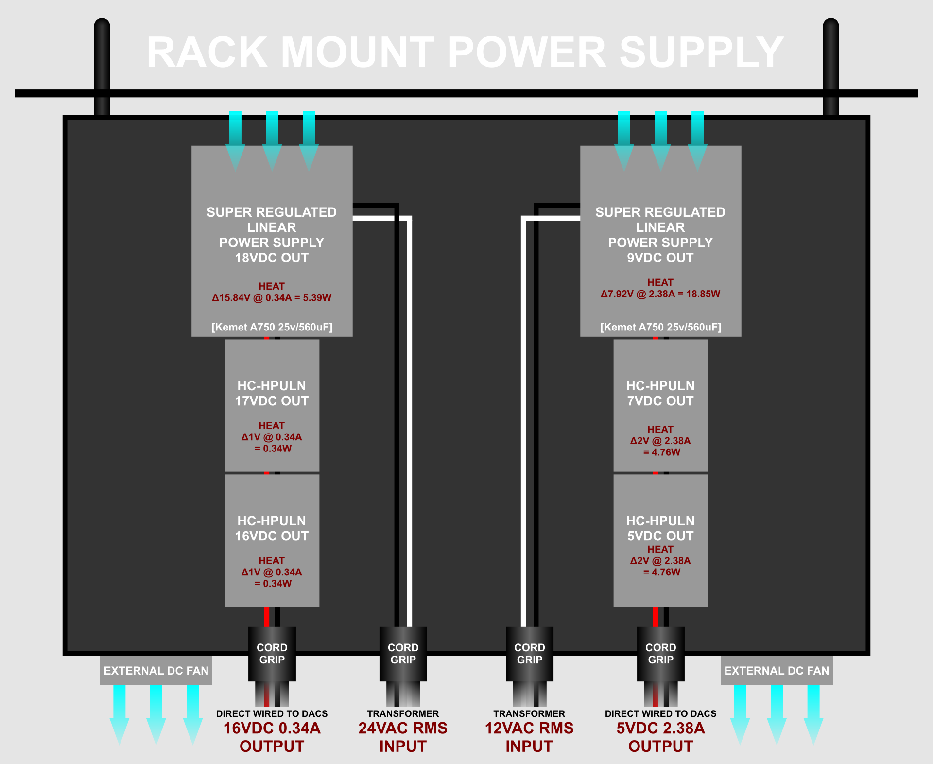
The entire server rack is enclosed for airflow control, and for sound control with the use of sound absorption. The fans are all silent and under-driven unless temp controllers kick in. How the entire server rack is set up, cool air is drawn up from the bottom front and sucked out the top back, with all of the individual racks drawing air from front to back.
What I could do is mount the fans outside of the rack housing and power them separate. Here's revised with these considerations...
The entire server rack is enclosed for airflow control, and for sound control with the use of sound absorption. The fans are all silent and under-driven unless temp controllers kick in. How the entire server rack is set up, cool air is drawn up from the bottom front and sucked out the top back, with all of the individual racks drawing air from front to back.
Last edited:
DC will always give you a draw-back in terms of SQ.
What ? How ?
I can see problem with PWM fan speed control circuits, but not a fixed DC voltage, even not ultra low noise.
Although "brushless" DC fans/motors are considered the cleanest in regard to EMI, I've suspected there's still potential for pulsed current draw when the DC fan magnets are more closely aligned in rotation. It appears measurable ripple is present with oscilloscope. See here. It's easy enough to just use an entire separate circuit for the fans.
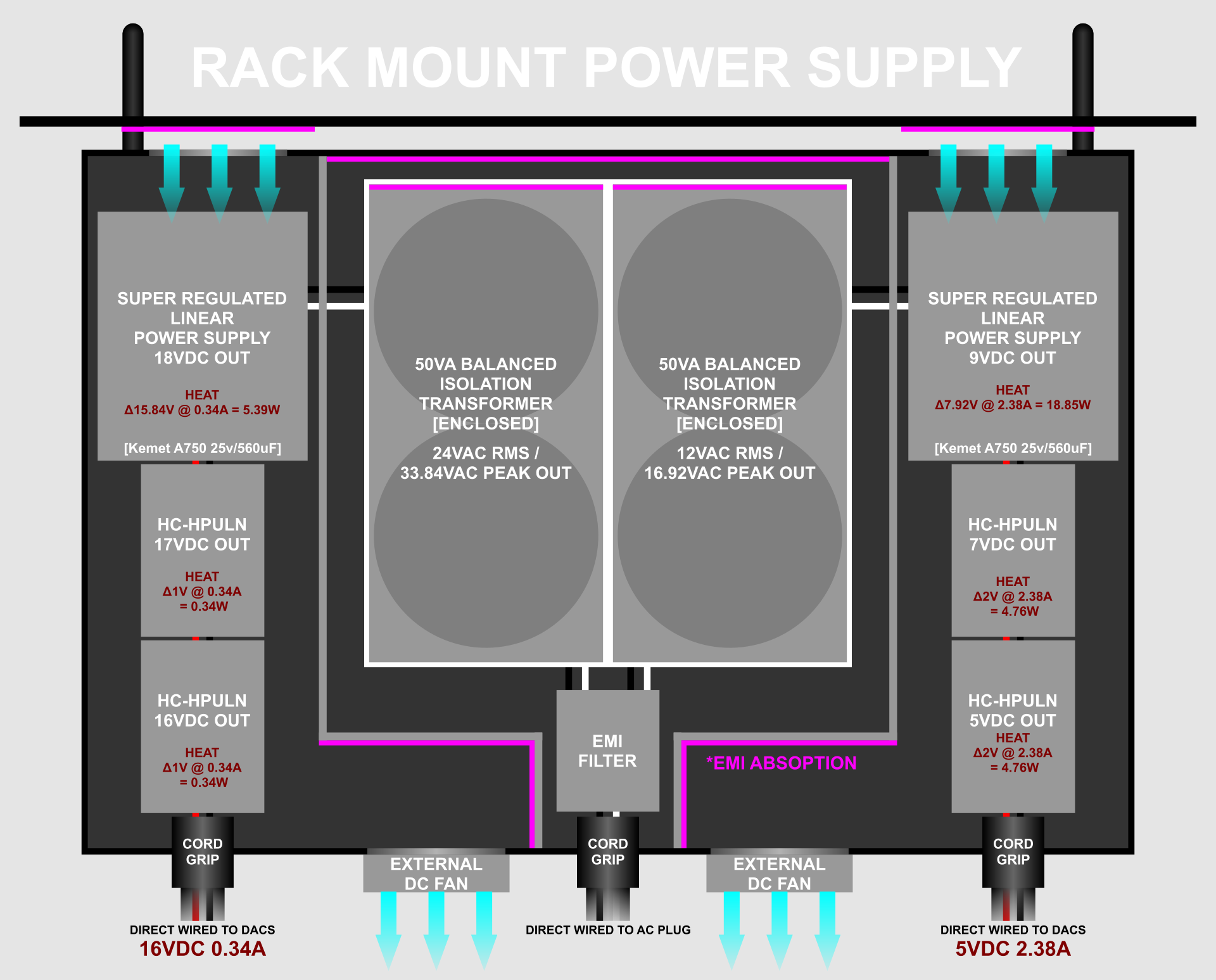
I've been reading up on transformer EMI, related to DACs and power supplies. It seems there's general consensus Toroidal transformers have low enough EMI to not be of significance even in the same enclosure as the other PS components, and any advantage in remote placement is more than offset by disadvantages of loop area and impedance, wherein it's generally best to keep everything wired closely. A shielded transformer seems to be more than adequate. Of course this is only a line of thought, but it's widely used, so I'm leaning toward a single self-contained rack unit with shielded transformers. DAC transformers also tend to be low VA rated anyhow. To be sure, I may as well add a second shield between the transformer enclosures and other PS components. I'll include EMI absorption on one plane of the transformer enclosures and on the reflecting planes of the air vent ports. DC fans still powered separately.
The problem is not DC in itself. The problem is when a single transformer powers several voltage regs powering different devices. For optimal SQ each volage reg combo should have its own transformer and power one device only to avoid transformer core artifacts.What ? How ?
I can see problem with PWM fan speed control circuits, but not a fixed DC voltage, even not ultra low noise.
I've been reading up on transformer EMI, related to DACs and power supplies. It seems there's general consensus Toroidal transformers have low enough EMI to not be of significance even in the same enclosure as the other PS components, and any advantage in remote placement is more than offset by disadvantages of loop area and impedance, wherein it's generally best to keep everything wired closely. A shielded transformer seems to be more than adequate. Of course this is only a line of thought, but it's widely used, so I'm leaning toward a single self-contained rack unit with shielded transformers. DAC transformers also tend to be low VA rated anyhow. To be sure, I may as well add a second shield between the transformer enclosures and other PS components. I'll include EMI absorption on one plane of the transformer enclosures and on the reflecting planes of the air vent ports. DC fans still powered separately.
This surely looks great to me! 🙂
- Home
- Vendor's Bazaar
- FS: „Ultra Low Noise“ Power Supply, LT3045 based PCB’s