The i2C wires are going to an Arduino controller. I use the code from Hifiduino.
My goal is to replace the Arduino controller and use the BBB with isolated i2C from Cronus. Problem is I have to learn Linux and programming language first.
The IP_S wires is just hooked up to a switch that I have to flip manually to change between spdif and i2s. I have a mux board for spdif mounted under the Cronus, as you can see from the pictures.
I see, clear now. Thank a lot. You made my day, Kaskade.
Is that asynchronous connection since we don't use MCK or I'm thinking the wrong direction?
Linux is not that nasty as you may think. Just install PuTTy and in a couple of weeks you are up to the task (now I see some sense in the commands I enter - at least, I could handle everything Miero wrote about).
Hi Russ,
I have a (stupid, maybe) question: could we use Cronus and Botic in the same way as OTTO-II in a Dual Mono config, in order to have DSD and PCM?
If I understand correctly, only 3 data lines on Cronus are used in case of BIIISE? Could we somehow use remaining? It would be one for common DCK, and two pairs for PCM or DSD's D1 and D2. And switching between them would be on Botic side?
Thanks,
Fedor
P.S. I have OTTO-II, and used it with Amanero before Cronus, but I'd prefer to leave it out")
I have a (stupid, maybe) question: could we use Cronus and Botic in the same way as OTTO-II in a Dual Mono config, in order to have DSD and PCM?
If I understand correctly, only 3 data lines on Cronus are used in case of BIIISE? Could we somehow use remaining? It would be one for common DCK, and two pairs for PCM or DSD's D1 and D2. And switching between them would be on Botic side?
Thanks,
Fedor
P.S. I have OTTO-II, and used it with Amanero before Cronus, but I'd prefer to leave it out
Last edited:
Oh, wait, I need to have some pin at high or low in order to drive OTTO's switch, depending on DSD playing or not.
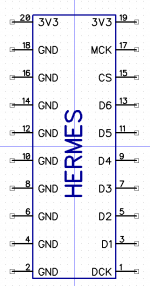
Since leds 1-3 on hermes-BBB are not used for now, and can be driven from Botic, is it possible to use one of them?
Or is there a more suited pin?
Yes. Each LED is controlled by a deliver chip that should give you enough current.
There are other pins available on the Hermes-BBB you could use as well.
Last edited:
Hi Rus,
I have BBB -> Hermes -> Cronus -> BIII as per attached picture
Miero's stock linux image, python scripts for ess9018 boot setup and volume control over i2c.
The problem is that for 48kHz multiples the sound is a little bit slow.
Using the following command in linux I can generate a 1kHz sine:
AUDIODEV=hw:0 play -r 96000 -n synth 60.0 sine 1000 gain 0
For 44.1kHz multiples everything is fine but for 48 kHz multiples I get a 920Hz sine as per second picture.
Another thing is that for 48kHz multiples after DAC start the music play with the normal pitch but the lock goes away after 1-2 seconds, but yesterday it stayed for 1-2 minutes... after 5-10 minutes I can get the lock but the pitch is away
I would use some advice for debugging the abnormal behaviour
1. first I plan to redo the soldering of the clock
but if this will not work which should be the next steps?
Thank you
I have BBB -> Hermes -> Cronus -> BIII as per attached picture
An externally hosted image should be here but it was not working when we last tested it.
Miero's stock linux image, python scripts for ess9018 boot setup and volume control over i2c.
The problem is that for 48kHz multiples the sound is a little bit slow.
Using the following command in linux I can generate a 1kHz sine:
AUDIODEV=hw:0 play -r 96000 -n synth 60.0 sine 1000 gain 0
For 44.1kHz multiples everything is fine but for 48 kHz multiples I get a 920Hz sine as per second picture.
An externally hosted image should be here but it was not working when we last tested it.
Another thing is that for 48kHz multiples after DAC start the music play with the normal pitch but the lock goes away after 1-2 seconds, but yesterday it stayed for 1-2 minutes... after 5-10 minutes I can get the lock but the pitch is away
I would use some advice for debugging the abnormal behaviour
1. first I plan to redo the soldering of the clock
but if this will not work which should be the next steps?
Thank you
Thanks, I will try, but why 44.1 (and SACD) is working as expected?
Later edit:
I confirm that the slower clock is in X1 position as per Brian's post
I looks like the wrong clock is being selected
Check that the CS (clock select) signal on the hermes header is changing as expected.
Later edit:
I confirm that the slower clock is in X1 position as per Brian's post
An externally hosted image should be here but it was not working when we last tested it.
Last edited:
Because that 44.1Khz time base clock is the one that is staying always selected.
Check that the CS signal is changing when you move from 44.1Khz multiple to 48Khz multiples.
At first CS signal is changing as expected, then the clock for 48Khz in garbled and BIII doesn't lock and finally it stops changing as you say it would.
Not sure I am following you exactly - but I would recommend you double check all the solder joints on the Rhea and the clock sockets. If CS signal is changing correctly (depending on time base of the audio signal) then the clock which is output to the BBB will change with it.
Not sure I am following you exactly - but I would recommend you double check all the solder joints on the Rhea and the clock sockets. If CS signal is changing correctly (depending on time base of the audio signal) then the clock which is output to the BBB will change with it.
I was trying to say that in three time points there are the following states:
T0 - right after power up - CS signal is changing as expected
T1 - some 2 up to 10 minutes after T0 - CS signal for 48kHz multiples becomes garbled
T2 - after 4-5 minutes after T1 - CS signal stops changing.
Both X1 and X2 are working as expected in T0, T1 and T2, I've checked them using the uper right hole.
Tommorow, as is past midnight here and tommorow morning I have to go to work, I will check all soldering points and see if anything changes.
Thank you
- Home
- More Vendors...
- Twisted Pear
- Cronus - It's about time.