This clocks group buy might be of intrest to future BBB cape users.
Will it all fit ?
I too, have been intently following your progress and quietly at that; being absorbed in other things: Like my BIII 8ch build (dual mono preferred). Became obvious that BIII's actual layout should hinge on workable Cape design, especially the dual-mono decision.
I have all the faith in you and Russ, Miero.
I don't really see the 10cm(3.9") limitation and the non-stackability as a defeating issue.
IF system layout is determined knowing ALL the physical/dimensional parameters.
So I shelved the BIII layout for awhile.
In my mind the Cape(s) can be mechanically positioned above the BIII(s)....... basically, Cape(s) hung on inboard 'roof' of enclosure.
The decision as to go with twin or single Legatos certainly complicates things.
But again BIII(s) could be mounted vertically (basically adjacent to Cape(s)).....to keep the distances down between dual BIII's with single Legato wiring.
It's certain that a 2-D layout won't get it. And certainly confusing lacking parameters.
With 30yrs CNC mach/prog & 3D solid Modeling; the min I2S line vectors will fall out for me.....once you two Pros design the really difficult task : The BOTIC
But I sensed (or was so confused) that multiple BBB's might be required !
So, what the hell.
I bought (4) BBB Rev B's in March and put 'em on the shelf, ....just in case.
Hoarding? No that's faith !
But I am worried that Rev C BBB's might be required (crossing fingers)
Charles
Last edited:
Figured simplicity with single BBB clocking would be paramount.
But clarify that if orientation can still be achieved with I2s lines< 10cm to (2) BIII's isn't dual 8ch DACs a feasibility?
I realize I was lost with any 2 BBB query, but local seller awaiting RevC had 4 RevB avail ...they're good barter now
But clarify that if orientation can still be achieved with I2s lines< 10cm to (2) BIII's isn't dual 8ch DACs a feasibility?
I realize I was lost with any 2 BBB query, but local seller awaiting RevC had 4 RevB avail ...they're good barter now
I don't really see the 10cm(3.9") limitation and the non-stackability as a defeating issue.
The 10cm number people throw around is a totally arbitrary number. The rule is: shorter is better, and don't cross noisy clock wires with any other wires (power, gnd, etc).
IF system layout is determined knowing ALL the physical/dimensional parameters.
We should be able to release more information about physical size very shortly. We are working on multi-board layout details now.
In my mind the Cape(s) can be mechanically positioned above the BIII(s).......
There will be direct mounting options for the B-III.
But I sensed (or was so confused) that multiple BBB's might be required !
As Miero said, this is not the case. One will do.
But I am worried that Rev C BBB's might be required (crossing fingers)
Not that either.
The 10cm number is not totally arbitrary. It's what one of the designers stated as the maximum trace length for which I2S was designed. And 10cm is still what many chip manufacturers (Samsung, Atmel) state as their maximum PCB trace length, for many other usages (besides I2S).
That said, the statement about I2S was made in the 80's. It was a time many people believed no PCB made in China could ever go beyond 50MHz. Ouch.
That said, the statement about I2S was made in the 80's. It was a time many people believed no PCB made in China could ever go beyond 50MHz. Ouch.
The 10cm number is not totally arbitrary. It's what one of the designers stated as the maximum trace length for which I2S was designed. And 10cm is still what many chip manufacturers (Samsung, Atmel) state as their maximum PCB trace length, for many other usages (besides I2S).
That said, the statement about I2S was made in the 80's. It was a time many people believed no PCB made in China could ever go beyond 50MHz. Ouch.
Do you have documentation of this? If such a statement was made, it was probably arbitrary as well.
It seems it would depend purely in the impedances and drive capability of the chips involved, as well as routing precautions taken (including shielding).
34 year old data, surely there's more recent
It's not 34 year old data.
I believe it to be a technical parameter of a 34 (or so) year old technical standard, which is quite different.
I recall quite a lot of discussion around this a few years ago but life is to short and there are too many audio projects to complete to make it worth trying to find again and the main thing is a viable, not too compromised, end solution and I believe there is the expertise here to deliver that to us.
One wants to have I2S transmission between two different components, the solution is to use LVDS signaling (balanced) as can be done using the Twisted Pear Audio Teleporter.
That's my current thinking, house the BBB/Botic in a separate chassis and connect to the DAC via teleporter modules. Flexible too.
Ray
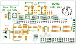
Ordering boards today. Here is the PCB in case there any last minute requests.
Since we only use P9 and I really needed to use both side of the PCB I offset the board so that just P9 is used and that way one can actually direct mount a B3. There are headers for Teleporter(MCK,BCK,D1,D2), B3, MCK, Rotary Encoder with switch, RST, PWR, ADC, I2C, and BATTERY.
I will post the schematics soon.
Cheers!
Russ
Attachments
- Status
- This old topic is closed. If you want to reopen this topic, contact a moderator using the "Report Post" button.
- Home
- More Vendors...
- Twisted Pear
- Building an open embedded audio applicance.