
There is still a capacitor in the signal path shorting AC signals, this is normal for pentode operation but it is still no current source...but it should be closer now... the higher the resistor the closer you will het at the expense of the voltage drop. So using a current source instead of the resistor can solve this.
@Koonw,
i do not understand what you want to say here, sorry i really am....
@Koonw,
i do not understand what you want to say here, sorry i really am....
Last edited:
Is this another hint?
I say you still hint a lot here and when a solution is already there #80?
@Lampie519 You can't understand because you not paying enough attention, in the least you could tell him how to bias the top tube properly, how do you do that?
In the end you don't get a better result other than floating screen.
Ok, now i get it !
Sure a seperate floating PSU will solve it but needs to be done for both sides and my guess is that Marco would like to have an easy way out so to speak.
And as we all know, a easy way out is always more complicated LOL....
Therefore my "hints" as i like to encourage and not offer a solution here...
In case floating power would be the only solution i would agree but as we can see there are other options and if we do not try we will never know if these work perfect in this case.
Please do not compare a Futterman poweramp with this tiny pentode amp... a screen of a ECF80 does not need much current so a current source will suffice here.
Anyway.... Thanks for beeing concerned, it is appreciated !
Best wishes,
Frank
The subject is Mu stage or follower, the idea is understand first the prior art and built, then only you can compare. The schematics by OP will mostly work if you don't get into clipping. The gain is not equal to Mu as output Z will suffer esp. smaller tubes. I have EL84 screen wired the same way but I could try the floating screen PSU to compare one day.
Have a nice day!
Have a nice day!
Hello,
I removed this capacitor connected between the grid and the cathode.
Then I made measurements and I was surprised by the values of the tensions.
I searched and checked my system but in vain.
So I tried triode mode.
And there it was the same surprise: There are excess volts between the anode of the pentode and the anode of the triode!
Where they come from ?


Hello,
I removed this capacitor connected between the grid and the cathode.
Then I made measurements and I was surprised by the values of the tensions.
I searched and checked my system but in vain.
So I tried triode mode.
And there it was the same surprise: There are excess volts between the anode of the pentode and the anode of the triode!
Where they come from ?
A pentode will draw current on G2... this is normal, therefore you need a low impedance source to drive it (if you want to drive it).
Therefore you always measure the cathode current in a pentode and not the anode current as you need to add the G2 and A to get the exact results...
See that experimenting is good sometimes?
It does not matter if everyone tells you what is best practice if you do not understand why...
Therefore i also do experiments like this sometimes just to get the touch of real world measurements, no simulator can beat that LOL....
Last edited:
There are 3 modes 1) Pentode, screen is made reference to cathode 2) Triode, screen is made reference to Plate 3) Ultra-Linear, screen is connected to tap of OT usually 60% from plate.
So a capacitor between screen and cathode makes it work in Pentode mode (max gain, as there is zero feedback from plate), else it's still in tridoe mode (depending on how the screen supply is wired). In floating screen PSU, the filtering cap is already connected between the 2 terminals, the capacitor can be omitted.
These are the fundamentals, do get familiar with theory. The safer way is to play with simulator I would say. My projects run the two thing together in last 10 years, before that I have hard time just like you")
So a capacitor between screen and cathode makes it work in Pentode mode (max gain, as there is zero feedback from plate), else it's still in tridoe mode (depending on how the screen supply is wired). In floating screen PSU, the filtering cap is already connected between the 2 terminals, the capacitor can be omitted.
These are the fundamentals, do get familiar with theory. The safer way is to play with simulator I would say. My projects run the two thing together in last 10 years, before that I have hard time just like you
Everyone would like to build a good amp LOL !
Not everyone succeded haha...
A White cathode follower makes use of a feedback mechanism between the upper tube and the lower one. I do not think it is a good sounding circuit but it is a low impedance one.
The next question is why would you need that kind of low output impedance anyway....
Always ask yourself what is needed not what you think is the most advanced circuit.
If you know what is required as interstage gain or buffer then you think about how to get there not the other way arround.
A mu follower has a low output impedance , why would you need an additional buffer?
What is the input impedance of the next stage or circuit you need to drive?
Last edited:
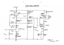
Is it possible to get schematic of your kimmel 6ah9 schematicYes that's what I used too. I had max B+=300V, so I put only 116V across the triode, about 155V across the pentode, so that the last 30V was across the anode resistor of the triode.
I biased both the pentode and the triode at -1V. That gave me 3mA through the triode and I guessed about 15mA through the pentode (the 6F12P dat sheets don't show screen current
30V and 3mA gives 10kOhm on the triode.
I have attached a cleaned up sketch of my test circuit (the original is very messy because I changed values a lot before I arrived at the final circuit). I was testing many pentode/triodes at the time. The 6F12P worked well, so did the 6KT8, and the 6KR8. My favourite was the 6AH9 compactron (mu=20).
I didn't use a second regulated supply for the screen of the 6F12P pentode (interesting idea) but just tapped it frpom the B+ as Alan suggested.
Yes ,I will do it for sure ,some decade ago I have KORATO audio (Serbia)mu stage preamp,
and was pleased with the sound but in some circumstances give it as a gift to my friend.
6ah9 pentode with it high transconductance is just alan kimmel proposed,
but I just wonder how are you pleased with triode linearity (let me know your observation) .Now I use fx audio tube03 as preamp on my DINAS speakers
The Dinas - Do I need a Subwoofer? - Toid's DIY Audio
and it is much better with tubes on D class amps then without it.
I do make some change on fx but want to go little bit further with 6ah9
mu stage and Janus Shunt Regulator Kit from Broskie
Zoran
- Home
- Amplifiers
- Tubes / Valves
- Mu stage driver